Coordinate transforms
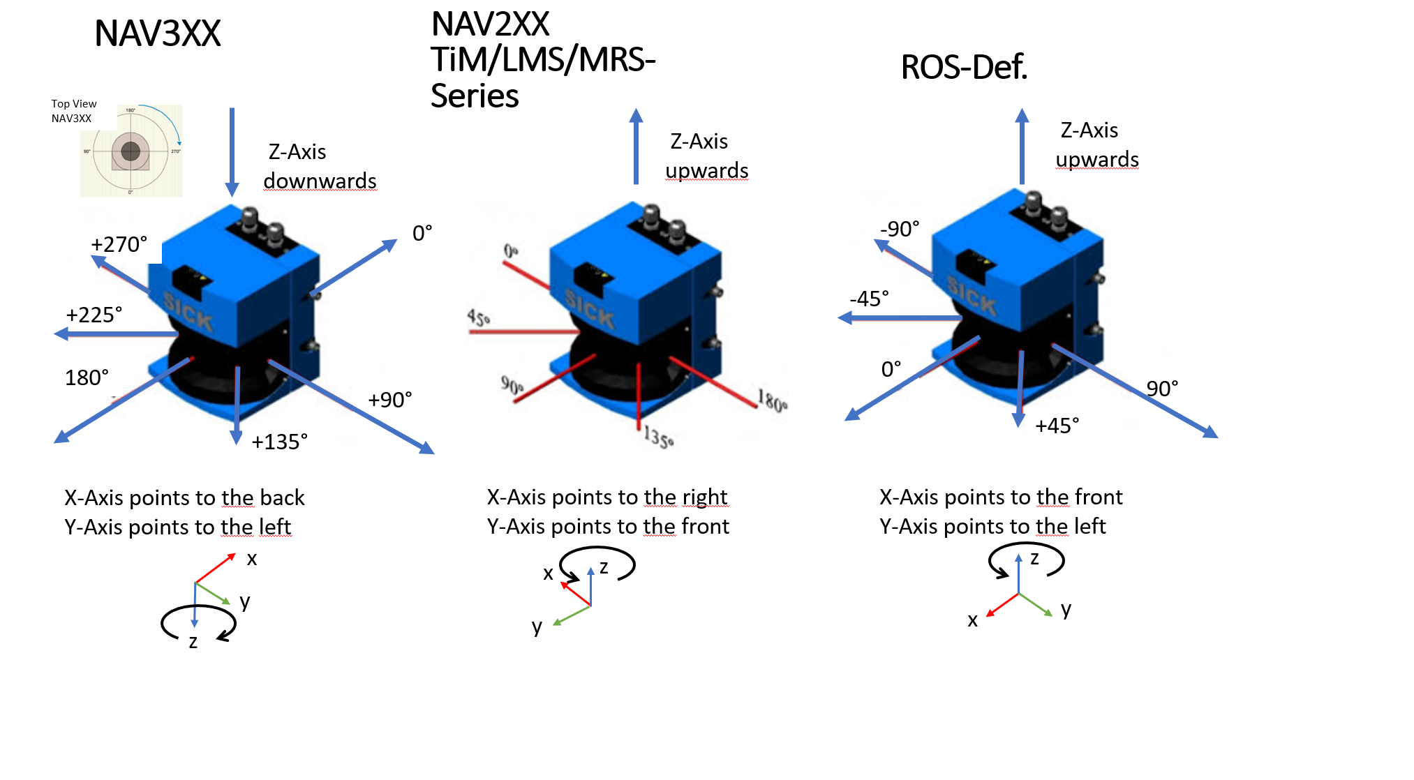
Different lidars use different coordinate systems. sick_scan_xd transforms all points of the published pointclouds to the ROS coordinate system, independant of the lidar. The following figure shows the commonly used coordinate systems:
An additional coordinate transform can be applied to the pointcloud. This optional transform can be used to transform the pointclouds into a user defined coordinate system. If the lidar is e.g. mounted on a vehicle, the pointclouds can be transformed into a vehicle coordinates.
An additional coordinate transform can be configured by a 6D pose (x, y, z, roll, pitch, yaw) with a translational part (x, y, z) in [m] and a rotational part (roll, pitch, yaw) in [rad].
If configured, it will transform the pointcloud from its “cloud” coordinates into user defined “world” coordinate system:
T[world,cloud] with P_world = T[world,cloud] * P_cloud (parent: world, child: cloud)
The final rotation is defined by: Rotation = Rot[yaw] * Rot[pitch] * Rot[roll] with roll = rotation about x-axis, pitch = rotation about y-axis and yaw = rotation about z-axis.
An additional transform can be configured in the launchfile, e.g.
<!-- Apply an additional transform to the cartesian pointcloud, default: "0,0,0,0,0,0" (i.e. no transform) -->
<!-- Note: add_transform_xyz_rpy is specified by 6D pose x, y, z, roll, pitch, yaw in [m] resp. [rad] -->
<!-- It transforms a 3D point in cloud coordinates to 3D point in user defined world coordinates: -->
<!-- add_transform_xyz_rpy := T[world,cloud] with parent "world" and child "cloud", i.e. P_world = T[world,cloud] * P_cloud -->
<param name="add_transform_xyz_rpy" type="string" value="0,0,0,0,0,0" />
Default value is "0,0,0,0,0,0", i.e. no additional transform will be applied.
The additional transform applies to cartesian lidar pointclouds and visualization marker (fields). It is NOT applied to polar pointclouds, radarscans, ldmrs objects or other messages.
Note that sick_scan_xd configures an additional transform using (x, y, z, roll, pitch, yaw). In contrast, the ROS static_transform_publisher uses commandline arguments in order x, y, z, yaw, pitch, roll.
Example using ROS static_transform_publisher with x=0, y=0, z=0, roll=15, pitch=-10, yaw=5 [deg]:
source /opt/ros/noetic/setup.bash
# static_transform_publisher x y z yaw pitch roll frame_id child_frame_id period_in_ms
# tf_echo <source_frame> <target_frame>
# rot_x = 5 deg: 0.0872665, rot_y = -10 deg: -0.1745329, rot_z = 15 deg: 0.2617994
rosrun tf static_transform_publisher 0 0 0 0.2617994 -0.1745329 0.0872665 parent_frame child_frame 100
rosrun tf tf_echo parent_frame child_frame
File trafo_example.py demonstrates how a transform can be computed.
For upside down mounted devices, the pointcloud can be rotated by 180 deg about the x axis (180 deg roll angle). This additional rotation is configured in the launch file using parameter add_transform_xyz_rpy with value "0,0,0,3.141592,0,0". sick_lrs_36x0_upside_down.launch and sick_lrs_36x1_upside_down.launch show examples for compensating the pointcloud of an upside down mounted device by a 180 deg rotation about the x axis.