Angle Compensation
Table of contents
Introduction
For measurements with the highest demands on the accuracy of the angle measurement, the devices of the NAV series allow compensation of slight angle deviations during a rotation. The compensation is determined by the three parameters.
Additive compensation by an angle offset
Sinusoidal correction by specifying the amplitude and phase of compensation
The three parameters are then used to calculate the compensation as follows:
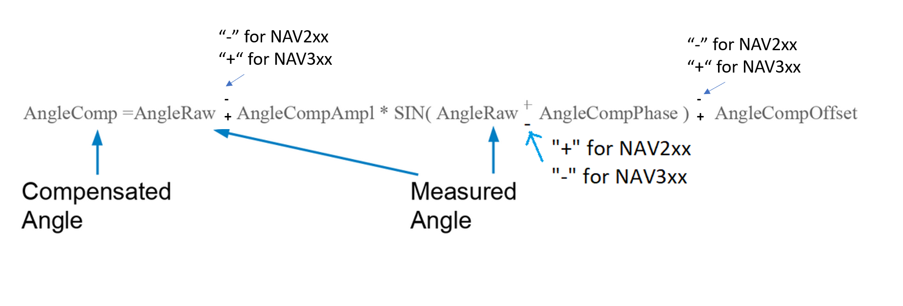
Offset and phase are given in [deg]
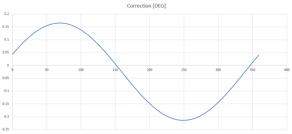
Example
The information is read from lidar by using the command sRN MCAngleCompSin.
The answer gives one amplitude, phase and offset compensation in tens of thousands.
The function reads
Amplitude-Parameter: +1893
Phase-Parameter: -210503
Offset-Parameter: -245
These corresponds to:
Amplitude-compensation: +0.1893
Phase-Compensation: -21.0503 [deg]
Offset-Compensation: -0.0245 [deg]
Comparing compensated vs. raw values
For the example the compensation function looks like this (X-Axis: measured angle [deg], Y-Axis: compensation in [deg])
Coordinate systems
For a better understanding of the data sheets of the different lidar systems the following drawings compare the different coordinate systems. Usually the scanners rotate counter-clockwise. The scanners of the NAV3xx series rotate clockwise. All coordinate systems following the right-hand rule, if the axis definition as shown in the picture is used.
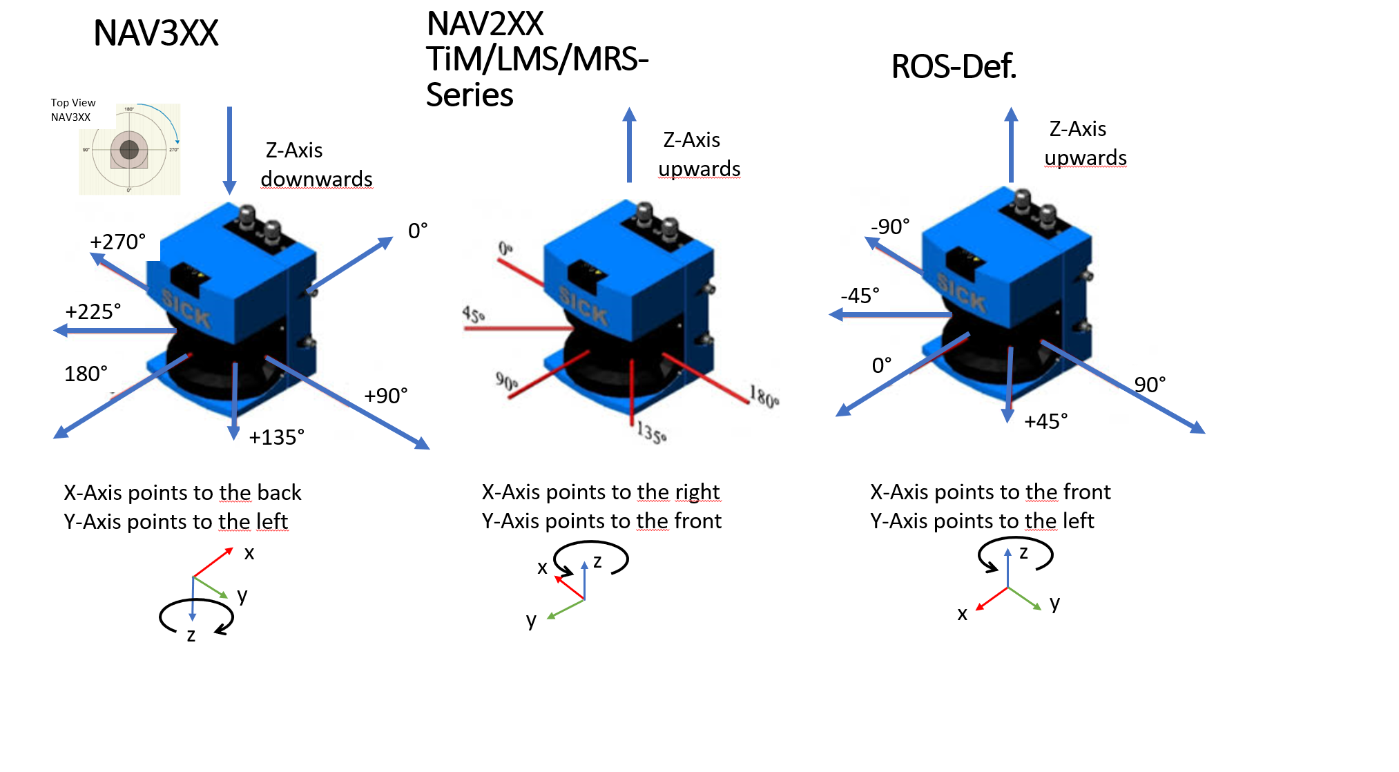
By means of simple matrix operations all axis orientations can be transformed into each other. But since we are only interested in the angle around the Z-axis, the conversions can be done as follows (CS = Coordinate System):
IN From |
Out To |
Operation |
Additional info |
|---|---|---|---|
ROS |
NAV3xx |
Out=-In+180° |
maps [-180°…180°] to [360°…0°] |
NAV3xx |
ROS |
Out=-In+180° |
maps [0°…360°] to [180°…-180°] |
ROS |
NAV2XX |
Out=In+90° |
|
NAV2xx |
ROS |
Out=In-90° |
Check compensation function
By using Octave ones can check the compensation function against the given values by exporting the value via a testbed function.