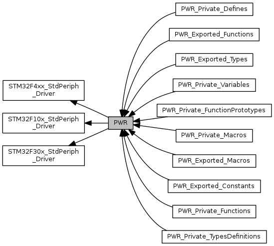
PWR driver modules. More...
|
Functions | |
| void | PWR_BackupAccessCmd (FunctionalState NewState) |
| Enables or disables access to the backup domain (RTC registers, RTC backup data registers and backup SRAM). More... | |
| void | PWR_ClearFlag (uint32_t PWR_FLAG) |
| Clears the PWR's pending flags. More... | |
| void | PWR_DeInit (void) |
| Deinitializes the PWR peripheral registers to their default reset values. More... | |
| void | PWR_EnterSleepMode (uint8_t PWR_SLEEPEntry) |
| Enters Sleep mode. More... | |
| void | PWR_EnterSTANDBYMode (void) |
| Enters STANDBY mode. More... | |
| void | PWR_EnterSTOPMode (uint32_t PWR_Regulator, uint8_t PWR_STOPEntry) |
| Enters STOP mode. More... | |
| FlagStatus | PWR_GetFlagStatus (uint32_t PWR_FLAG) |
| Checks whether the specified PWR flag is set or not. More... | |
| void | PWR_PVDCmd (FunctionalState NewState) |
| Enables or disables the Power Voltage Detector(PVD). More... | |
| void | PWR_PVDLevelConfig (uint32_t PWR_PVDLevel) |
| Configures the voltage threshold detected by the Power Voltage Detector(PVD). More... | |
| void | PWR_WakeUpPinCmd (uint32_t PWR_WakeUpPin, FunctionalState NewState) |
| Enables or disables the WakeUp Pin functionality. More... | |
Detailed Description
PWR driver modules.
Macro Definition Documentation
| #define BRE_BitNumber 0x09 |
Definition at line 83 of file stm32f4xx_pwr.c.
| #define CR_DBP_BB (PERIPH_BB_BASE + (CR_OFFSET * 32) + (DBP_BitNumber * 4)) |
Definition at line 58 of file stm32f30x_pwr.c.
| #define CR_DBP_BB (PERIPH_BB_BASE + (CR_OFFSET * 32) + (DBP_BitNumber * 4)) |
Definition at line 60 of file stm32f4xx_pwr.c.
| #define CR_DS_MASK ((uint32_t)0xFFFFFFFC) |
Definition at line 67 of file stm32f30x_pwr.c.
| #define CR_DS_MASK ((uint32_t)0xFFFFFFFC) |
Definition at line 89 of file stm32f4xx_pwr.c.
| #define CR_FPDS_BB (PERIPH_BB_BASE + (CR_OFFSET * 32) + (FPDS_BitNumber * 4)) |
Definition at line 68 of file stm32f4xx_pwr.c.
| #define CR_OFFSET (PWR_OFFSET + 0x00) |
Definition at line 56 of file stm32f30x_pwr.c.
| #define CR_OFFSET (PWR_OFFSET + 0x00) |
Definition at line 58 of file stm32f4xx_pwr.c.
| #define CR_PLS_MASK ((uint32_t)0xFFFFFF1F) |
Definition at line 68 of file stm32f30x_pwr.c.
| #define CR_PLS_MASK ((uint32_t)0xFFFFFF1F) |
Definition at line 90 of file stm32f4xx_pwr.c.
| #define CR_PMODE_BB (PERIPH_BB_BASE + (CR_OFFSET * 32) + (PMODE_BitNumber * 4)) |
Definition at line 72 of file stm32f4xx_pwr.c.
| #define CR_PVDE_BB (PERIPH_BB_BASE + (CR_OFFSET * 32) + (PVDE_BitNumber * 4)) |
Definition at line 62 of file stm32f30x_pwr.c.
| #define CR_PVDE_BB (PERIPH_BB_BASE + (CR_OFFSET * 32) + (PVDE_BitNumber * 4)) |
Definition at line 64 of file stm32f4xx_pwr.c.
| #define CR_VOS_MASK ((uint32_t)0xFFFF3FFF) |
Definition at line 91 of file stm32f4xx_pwr.c.
| #define CSR_BRE_BB (PERIPH_BB_BASE + (CSR_OFFSET * 32) + (BRE_BitNumber * 4)) |
Definition at line 84 of file stm32f4xx_pwr.c.
| #define CSR_EWUP_BB (PERIPH_BB_BASE + (CSR_OFFSET * 32) + (EWUP_BitNumber * 4)) |
Definition at line 80 of file stm32f4xx_pwr.c.
| #define CSR_OFFSET (PWR_OFFSET + 0x04) |
Definition at line 78 of file stm32f4xx_pwr.c.
| #define DBP_BitNumber 0x08 |
Definition at line 57 of file stm32f30x_pwr.c.
| #define DBP_BitNumber 0x08 |
Definition at line 59 of file stm32f4xx_pwr.c.
| #define EWUP_BitNumber 0x08 |
Definition at line 79 of file stm32f4xx_pwr.c.
| #define FPDS_BitNumber 0x09 |
Definition at line 67 of file stm32f4xx_pwr.c.
| #define PMODE_BitNumber 0x0E |
Definition at line 71 of file stm32f4xx_pwr.c.
| #define PVDE_BitNumber 0x04 |
Definition at line 61 of file stm32f30x_pwr.c.
| #define PVDE_BitNumber 0x04 |
Definition at line 63 of file stm32f4xx_pwr.c.
| #define PWR_OFFSET (PWR_BASE - PERIPH_BASE) |
Definition at line 51 of file stm32f30x_pwr.c.
| #define PWR_OFFSET (PWR_BASE - PERIPH_BASE) |
Definition at line 53 of file stm32f4xx_pwr.c.
Function Documentation
| void PWR_BackupAccessCmd | ( | FunctionalState | NewState | ) |
Enables or disables access to the backup domain (RTC registers, RTC backup data registers and backup SRAM).
Enables or disables access to the RTC and backup registers.
- Note
- If the HSE divided by 2, 3, ..31 is used as the RTC clock, the Backup Domain Access should be kept enabled.
- Parameters
-
NewState new state of the access to the backup domain. This parameter can be: ENABLE or DISABLE.
- Return values
-
None
- Note
- If the HSE divided by 32 is used as the RTC clock, the Backup Domain Access should be kept enabled.
- Parameters
-
NewState new state of the access to the RTC and backup registers. This parameter can be: ENABLE or DISABLE.
- Return values
-
None Enables or disables access to the backup domain (RTC registers, RTC backup data registers and backup SRAM).
- Parameters
-
NewState new state of the access to the RTC and backup registers. This parameter can be: ENABLE or DISABLE.
- Return values
-
None
Definition at line 142 of file stm32f4xx_pwr.c.
| void PWR_ClearFlag | ( | uint32_t | PWR_FLAG | ) |
Clears the PWR's pending flags.
- Parameters
-
PWR_FLAG specifies the flag to clear. This parameter can be one of the following values: - PWR_FLAG_WU: Wake Up flag
- PWR_FLAG_SB: StandBy flag
- Return values
-
None
Definition at line 654 of file stm32f4xx_pwr.c.
| void PWR_DeInit | ( | void | ) |
Deinitializes the PWR peripheral registers to their default reset values.
- Parameters
-
None
- Return values
-
None
Definition at line 127 of file stm32f4xx_pwr.c.
| void PWR_EnterSleepMode | ( | uint8_t | PWR_SLEEPEntry | ) |
Enters Sleep mode.
- Note
- In Sleep mode, all I/O pins keep the same state as in Run mode.
- Parameters
-
PWR_SLEEPEntry specifies if SLEEP mode in entered with WFI or WFE instruction. This parameter can be one of the following values: - PWR_SLEEPEntry_WFI: enter SLEEP mode with WFI instruction
- PWR_SLEEPEntry_WFE: enter SLEEP mode with WFE instruction
- Return values
-
None
Definition at line 351 of file stm32f30x_pwr.c.
| void PWR_EnterSTANDBYMode | ( | void | ) |
Enters STANDBY mode.
- Note
- In Standby mode, all I/O pins are high impedance except for:
- Reset pad (still available)
- RTC_AF1 pin (PC13) if configured for tamper, time-stamp, RTC Alarm out, or RTC clock calibration out.
- RTC_AF2 pin (PI8) if configured for tamper or time-stamp.
- WKUP pin 1 (PA0) if enabled.
- Parameters
-
None
- Return values
-
None
- Parameters
-
None
- Return values
-
None
- Note
- In Standby mode, all I/O pins are high impedance except for:
- Reset pad (still available)
- RTC_AF1 pin (PC13) if configured for Wakeup pin 2 (WKUP2), tamper, time-stamp, RTC Alarm out, or RTC clock calibration out.
- WKUP pin 1 (PA0) and WKUP pin 3 (PE6), if enabled.
- Parameters
-
None
- Return values
-
None
Definition at line 570 of file stm32f4xx_pwr.c.
| void PWR_EnterSTOPMode | ( | uint32_t | PWR_Regulator, |
| uint8_t | PWR_STOPEntry | ||
| ) |
Enters STOP mode.
- Note
- In Stop mode, all I/O pins keep the same state as in Run mode.
- When exiting Stop mode by issuing an interrupt or a wakeup event, the HSI RC oscillator is selected as system clock.
- When the voltage regulator operates in low power mode, an additional startup delay is incurred when waking up from Stop mode. By keeping the internal regulator ON during Stop mode, the consumption is higher although the startup time is reduced.
- Parameters
-
PWR_Regulator specifies the regulator state in STOP mode. This parameter can be one of the following values: - PWR_Regulator_ON: STOP mode with regulator ON
- PWR_Regulator_LowPower: STOP mode with regulator in low power mode
PWR_STOPEntry specifies if STOP mode in entered with WFI or WFE instruction. This parameter can be one of the following values: - PWR_STOPEntry_WFI: enter STOP mode with WFI instruction
- PWR_STOPEntry_WFE: enter STOP mode with WFE instruction
- Return values
-
None
Definition at line 522 of file stm32f4xx_pwr.c.
| FlagStatus PWR_GetFlagStatus | ( | uint32_t | PWR_FLAG | ) |
Checks whether the specified PWR flag is set or not.
- Parameters
-
PWR_FLAG specifies the flag to check. This parameter can be one of the following values: - PWR_FLAG_WU: Wake Up flag. This flag indicates that a wakeup event was received from the WKUP pin or from the RTC alarm (Alarm A or Alarm B), RTC Tamper event, RTC TimeStamp event or RTC Wakeup. An additional wakeup event is detected if the WKUP pin is enabled (by setting the EWUP bit) when the WKUP pin level is already high.
- PWR_FLAG_SB: StandBy flag. This flag indicates that the system was resumed from StandBy mode.
- PWR_FLAG_PVDO: PVD Output. This flag is valid only if PVD is enabled by the PWR_PVDCmd() function. The PVD is stopped by Standby mode For this reason, this bit is equal to 0 after Standby or reset until the PVDE bit is set.
- PWR_FLAG_BRR: Backup regulator ready flag. This bit is not reset when the device wakes up from Standby mode or by a system reset or power reset.
- PWR_FLAG_VOSRDY: This flag indicates that the Regulator voltage scaling output selection is ready.
- Return values
-
The new state of PWR_FLAG (SET or RESET).
- Parameters
-
PWR_FLAG specifies the flag to check. This parameter can be one of the following values: - PWR_FLAG_WU: Wake Up flag
- PWR_FLAG_SB: StandBy flag
- PWR_FLAG_PVDO: PVD Output
- Return values
-
The new state of PWR_FLAG (SET or RESET).
- Parameters
-
PWR_FLAG specifies the flag to check. This parameter can be one of the following values: - PWR_FLAG_WU: Wake Up flag. This flag indicates that a wakeup event was received from the WKUP pin or from the RTC alarm (Alarm A or Alarm B), RTC Tamper event, RTC TimeStamp event or RTC Wakeup.
- PWR_FLAG_SB: StandBy flag. This flag indicates that the system was resumed from StandBy mode.
- PWR_FLAG_PVDO: PVD Output. This flag is valid only if PVD is enabled by the PWR_PVDCmd() function.
- PWR_FLAG_VREFINTRDY: Internal Voltage Reference Ready flag. This flag indicates the state of the internal voltage reference, VREFINT.
- Return values
-
The new state of PWR_FLAG (SET or RESET).
Definition at line 627 of file stm32f4xx_pwr.c.
| void PWR_PVDCmd | ( | FunctionalState | NewState | ) |
Enables or disables the Power Voltage Detector(PVD).
- Parameters
-
NewState new state of the PVD. This parameter can be: ENABLE or DISABLE.
- Return values
-
None
Definition at line 215 of file stm32f4xx_pwr.c.
| void PWR_PVDLevelConfig | ( | uint32_t | PWR_PVDLevel | ) |
Configures the voltage threshold detected by the Power Voltage Detector(PVD).
- Parameters
-
PWR_PVDLevel specifies the PVD detection level This parameter can be one of the following values: - PWR_PVDLevel_0
- PWR_PVDLevel_1
- PWR_PVDLevel_2
- PWR_PVDLevel_3
- PWR_PVDLevel_4
- PWR_PVDLevel_5
- PWR_PVDLevel_6
- PWR_PVDLevel_7
- Note
- Refer to the electrical characteristics of your device datasheet for more details about the voltage threshold corresponding to each detection level.
- Return values
-
None
- Parameters
-
PWR_PVDLevel specifies the PVD detection level This parameter can be one of the following values: - PWR_PVDLevel_0: PVD detection level set to 2.18V
- PWR_PVDLevel_1: PVD detection level set to 2.28V
- PWR_PVDLevel_2: PVD detection level set to 2.38V
- PWR_PVDLevel_3: PVD detection level set to 2.48V
- PWR_PVDLevel_4: PVD detection level set to 2.58V
- PWR_PVDLevel_5: PVD detection level set to 2.68V
- PWR_PVDLevel_6: PVD detection level set to 2.78V
- PWR_PVDLevel_7: PVD detection level set to 2.88V
- Return values
-
None
- Parameters
-
PWR_PVDLevel specifies the PVD detection level This parameter can be one of the following values: - PWR_PVDLevel_2V2: PVD detection level set to 2.2V
- PWR_PVDLevel_2V3: PVD detection level set to 2.3V
- PWR_PVDLevel_2V4: PVD detection level set to 2.4V
- PWR_PVDLevel_2V5: PVD detection level set to 2.5V
- PWR_PVDLevel_2V6: PVD detection level set to 2.6V
- PWR_PVDLevel_2V7: PVD detection level set to 2.7V
- PWR_PVDLevel_2V8: PVD detection level set to 2.8V
- PWR_PVDLevel_2V9: PVD detection level set to 2.9V
- Return values
-
None
Definition at line 190 of file stm32f4xx_pwr.c.
| void PWR_WakeUpPinCmd | ( | uint32_t | PWR_WakeUpPin, |
| FunctionalState | NewState | ||
| ) |
Enables or disables the WakeUp Pin functionality.
- Parameters
-
PWR_WakeUpPin specifies the WakeUpPin. This parameter can be: PWR_WakeUpPin_1, PWR_WakeUpPin_2 or PWR_WakeUpPin_3. NewState new state of the WakeUp Pin functionality. This parameter can be: ENABLE or DISABLE.
- Return values
-
None
Definition at line 219 of file stm32f30x_pwr.c.