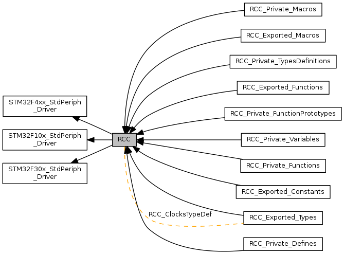
RCC driver modules. More...
|
Classes | |
| struct | RCC_ClocksTypeDef |
Functions | |
| void | RCC_AdjustHSICalibrationValue (uint8_t HSICalibrationValue) |
| Adjusts the Internal High Speed oscillator (HSI) calibration value. More... | |
| void | RCC_AHB1PeriphClockCmd (uint32_t RCC_AHB1Periph, FunctionalState NewState) |
| Enables or disables the AHB1 peripheral clock. More... | |
| void | RCC_AHB1PeriphClockLPModeCmd (uint32_t RCC_AHB1Periph, FunctionalState NewState) |
| Enables or disables the AHB1 peripheral clock during Low Power (Sleep) mode. More... | |
| void | RCC_AHB1PeriphResetCmd (uint32_t RCC_AHB1Periph, FunctionalState NewState) |
| Forces or releases AHB1 peripheral reset. More... | |
| void | RCC_AHB2PeriphClockCmd (uint32_t RCC_AHB2Periph, FunctionalState NewState) |
| Enables or disables the AHB2 peripheral clock. More... | |
| void | RCC_AHB2PeriphClockLPModeCmd (uint32_t RCC_AHB2Periph, FunctionalState NewState) |
| Enables or disables the AHB2 peripheral clock during Low Power (Sleep) mode. More... | |
| void | RCC_AHB2PeriphResetCmd (uint32_t RCC_AHB2Periph, FunctionalState NewState) |
| Forces or releases AHB2 peripheral reset. More... | |
| void | RCC_AHB3PeriphClockCmd (uint32_t RCC_AHB3Periph, FunctionalState NewState) |
| Enables or disables the AHB3 peripheral clock. More... | |
| void | RCC_AHB3PeriphClockLPModeCmd (uint32_t RCC_AHB3Periph, FunctionalState NewState) |
| Enables or disables the AHB3 peripheral clock during Low Power (Sleep) mode. More... | |
| void | RCC_AHB3PeriphResetCmd (uint32_t RCC_AHB3Periph, FunctionalState NewState) |
| Forces or releases AHB3 peripheral reset. More... | |
| void | RCC_APB1PeriphClockCmd (uint32_t RCC_APB1Periph, FunctionalState NewState) |
| Enables or disables the Low Speed APB (APB1) peripheral clock. More... | |
| void | RCC_APB1PeriphClockLPModeCmd (uint32_t RCC_APB1Periph, FunctionalState NewState) |
| Enables or disables the APB1 peripheral clock during Low Power (Sleep) mode. More... | |
| void | RCC_APB1PeriphResetCmd (uint32_t RCC_APB1Periph, FunctionalState NewState) |
| Forces or releases Low Speed APB (APB1) peripheral reset. More... | |
| void | RCC_APB2PeriphClockCmd (uint32_t RCC_APB2Periph, FunctionalState NewState) |
| Enables or disables the High Speed APB (APB2) peripheral clock. More... | |
| void | RCC_APB2PeriphClockLPModeCmd (uint32_t RCC_APB2Periph, FunctionalState NewState) |
| Enables or disables the APB2 peripheral clock during Low Power (Sleep) mode. More... | |
| void | RCC_APB2PeriphResetCmd (uint32_t RCC_APB2Periph, FunctionalState NewState) |
| Forces or releases High Speed APB (APB2) peripheral reset. More... | |
| void | RCC_BackupResetCmd (FunctionalState NewState) |
| Forces or releases the Backup domain reset. More... | |
| void | RCC_ClearFlag (void) |
| Clears the RCC reset flags. The reset flags are: RCC_FLAG_PINRST, RCC_FLAG_PORRST, RCC_FLAG_SFTRST, RCC_FLAG_IWDGRST, RCC_FLAG_WWDGRST, RCC_FLAG_LPWRRST. More... | |
| void | RCC_ClearITPendingBit (uint8_t RCC_IT) |
| Clears the RCC's interrupt pending bits. More... | |
| void | RCC_ClockSecuritySystemCmd (FunctionalState NewState) |
| Enables or disables the Clock Security System. More... | |
| void | RCC_DeInit (void) |
| Resets the RCC clock configuration to the default reset state. More... | |
| void | RCC_GetClocksFreq (RCC_ClocksTypeDef *RCC_Clocks) |
| Returns the frequencies of different on chip clocks; SYSCLK, HCLK, PCLK1 and PCLK2. More... | |
| FlagStatus | RCC_GetFlagStatus (uint8_t RCC_FLAG) |
| Checks whether the specified RCC flag is set or not. More... | |
| ITStatus | RCC_GetITStatus (uint8_t RCC_IT) |
| Checks whether the specified RCC interrupt has occurred or not. More... | |
| uint8_t | RCC_GetSYSCLKSource (void) |
| Returns the clock source used as system clock. More... | |
| void | RCC_HCLKConfig (uint32_t RCC_SYSCLK) |
| Configures the AHB clock (HCLK). More... | |
| void | RCC_HSEConfig (uint8_t RCC_HSE) |
| Configures the External High Speed oscillator (HSE). More... | |
| void | RCC_HSICmd (FunctionalState NewState) |
| Enables or disables the Internal High Speed oscillator (HSI). More... | |
| void | RCC_ITConfig (uint8_t RCC_IT, FunctionalState NewState) |
| Enables or disables the specified RCC interrupts. More... | |
| void | RCC_LSEConfig (uint8_t RCC_LSE) |
| Configures the External Low Speed oscillator (LSE). More... | |
| void | RCC_LSEModeConfig (uint8_t RCC_Mode) |
| Configures the External Low Speed oscillator mode (LSE mode). More... | |
| void | RCC_LSICmd (FunctionalState NewState) |
| Enables or disables the Internal Low Speed oscillator (LSI). More... | |
| void | RCC_LTDCCLKDivConfig (uint32_t RCC_PLLSAIDivR) |
| Configures the LTDC clock Divider coming from PLLSAI. More... | |
| void | RCC_MCO1Config (uint32_t RCC_MCO1Source, uint32_t RCC_MCO1Div) |
| Selects the clock source to output on MCO1 pin(PA8). More... | |
| void | RCC_MCO2Config (uint32_t RCC_MCO2Source, uint32_t RCC_MCO2Div) |
| Selects the clock source to output on MCO2 pin(PC9). More... | |
| void | RCC_PCLK1Config (uint32_t RCC_HCLK) |
| Configures the Low Speed APB clock (PCLK1). More... | |
| void | RCC_PCLK2Config (uint32_t RCC_HCLK) |
| Configures the High Speed APB clock (PCLK2). More... | |
| void | RCC_PLLCmd (FunctionalState NewState) |
| Enables or disables the main PLL. More... | |
| void | RCC_PLLConfig (uint32_t RCC_PLLSource, uint32_t PLLM, uint32_t PLLN, uint32_t PLLP, uint32_t PLLQ) |
| Configures the main PLL clock source, multiplication and division factors. More... | |
| void | RCC_PLLI2SCmd (FunctionalState NewState) |
| Enables or disables the PLLI2S. More... | |
| void | RCC_PLLI2SConfig (uint32_t PLLI2SN, uint32_t PLLI2SR) |
| Configures the PLLI2S clock multiplication and division factors. More... | |
| void | RCC_PLLSAICmd (FunctionalState NewState) |
| Enables or disables the PLLSAI. More... | |
| void | RCC_RTCCLKCmd (FunctionalState NewState) |
| Enables or disables the RTC clock. More... | |
| void | RCC_RTCCLKConfig (uint32_t RCC_RTCCLKSource) |
| Configures the RTC clock (RTCCLK). More... | |
| void | RCC_SAIPLLI2SClkDivConfig (uint32_t RCC_PLLI2SDivQ) |
| Configures the SAI clock Divider coming from PLLI2S. More... | |
| void | RCC_SAIPLLSAIClkDivConfig (uint32_t RCC_PLLSAIDivQ) |
| Configures the SAI clock Divider coming from PLLSAI. More... | |
| void | RCC_SYSCLKConfig (uint32_t RCC_SYSCLKSource) |
| Configures the system clock (SYSCLK). More... | |
| void | RCC_TIMCLKPresConfig (uint32_t RCC_TIMCLKPrescaler) |
| Configures the Timers clocks prescalers selection. More... | |
| ErrorStatus | RCC_WaitForHSEStartUp (void) |
| Waits for HSE start-up. More... | |
Variables | |
| static __I uint16_t | ADCPrescTable [16] = {1, 2, 4, 6, 8, 10, 12, 16, 32, 64, 128, 256, 0, 0, 0, 0 } |
| static __I uint8_t | APBAHBPrescTable [16] = {0, 0, 0, 0, 1, 2, 3, 4, 1, 2, 3, 4, 6, 7, 8, 9} |
| static __I uint8_t | APBAHBPrescTable [16] = {0, 0, 0, 0, 1, 2, 3, 4, 1, 2, 3, 4, 6, 7, 8, 9} |
| static __I uint8_t | APBAHBPrescTable [16] = {0, 0, 0, 0, 1, 2, 3, 4, 1, 2, 3, 4, 6, 7, 8, 9} |
Detailed Description
RCC driver modules.
Macro Definition Documentation
| #define BDCR_ADDRESS (PERIPH_BASE + BDCR_OFFSET) |
Definition at line 133 of file STM32F4xx_StdPeriph_Driver/src/stm32f4xx_rcc.c.
| #define BDCR_ADDRESS (PERIPH_BASE + BDCR_OFFSET) |
Definition at line 149 of file CMSIS/CM4/DeviceSupport/ST/STM32F4xx/stm32f4xx_rcc.c.
| #define BDCR_BDRST_BB (PERIPH_BB_BASE + (BDCR_OFFSET * 32) + (BDRST_BitNumber * 4)) |
Definition at line 102 of file STM32F4xx_StdPeriph_Driver/src/stm32f4xx_rcc.c.
| #define BDCR_BDRST_BB (PERIPH_BB_BASE + (BDCR_OFFSET * 32) + (BDRST_BitNumber * 4)) |
Definition at line 106 of file CMSIS/CM4/DeviceSupport/ST/STM32F4xx/stm32f4xx_rcc.c.
| #define BDCR_BDRST_BB (PERIPH_BB_BASE + (BDCR_OFFSET * 32) + (BDRST_BitNumber * 4)) |
Definition at line 107 of file stm32f30x_rcc.c.
| #define BDCR_OFFSET (RCC_OFFSET + 0x70) |
Definition at line 97 of file STM32F4xx_StdPeriph_Driver/src/stm32f4xx_rcc.c.
| #define BDCR_OFFSET (RCC_OFFSET + 0x70) |
Definition at line 101 of file CMSIS/CM4/DeviceSupport/ST/STM32F4xx/stm32f4xx_rcc.c.
| #define BDCR_OFFSET (RCC_OFFSET + 0x20) |
Definition at line 101 of file stm32f30x_rcc.c.
| #define BDCR_RTCEN_BB (PERIPH_BB_BASE + (BDCR_OFFSET * 32) + (RTCEN_BitNumber * 4)) |
Definition at line 99 of file STM32F4xx_StdPeriph_Driver/src/stm32f4xx_rcc.c.
| #define BDCR_RTCEN_BB (PERIPH_BB_BASE + (BDCR_OFFSET * 32) + (RTCEN_BitNumber * 4)) |
Definition at line 103 of file CMSIS/CM4/DeviceSupport/ST/STM32F4xx/stm32f4xx_rcc.c.
| #define BDCR_RTCEN_BB (PERIPH_BB_BASE + (BDCR_OFFSET * 32) + (RTCEN_BitNumber * 4)) |
Definition at line 103 of file stm32f30x_rcc.c.
| #define BDRST_BitNumber 0x10 |
Definition at line 101 of file STM32F4xx_StdPeriph_Driver/src/stm32f4xx_rcc.c.
| #define BDRST_BitNumber 0x10 |
Definition at line 105 of file CMSIS/CM4/DeviceSupport/ST/STM32F4xx/stm32f4xx_rcc.c.
| #define BDRST_BitNumber 0x10 |
Definition at line 106 of file stm32f30x_rcc.c.
| #define CFGR_BYTE3_ADDRESS ((uint32_t)0x40021007) |
Definition at line 121 of file stm32f30x_rcc.c.
| #define CFGR_I2SSRC_BB (PERIPH_BB_BASE + (CFGR_OFFSET * 32) + (I2SSRC_BitNumber * 4)) |
Definition at line 93 of file STM32F4xx_StdPeriph_Driver/src/stm32f4xx_rcc.c.
| #define CFGR_I2SSRC_BB (PERIPH_BB_BASE + (CFGR_OFFSET * 32) + (I2SSRC_BitNumber * 4)) |
Definition at line 96 of file stm32f30x_rcc.c.
| #define CFGR_I2SSRC_BB (PERIPH_BB_BASE + (CFGR_OFFSET * 32) + (I2SSRC_BitNumber * 4)) |
Definition at line 97 of file CMSIS/CM4/DeviceSupport/ST/STM32F4xx/stm32f4xx_rcc.c.
| #define CFGR_MCO1_RESET_MASK ((uint32_t)0xF89FFFFF) |
Definition at line 118 of file STM32F4xx_StdPeriph_Driver/src/stm32f4xx_rcc.c.
| #define CFGR_MCO1_RESET_MASK ((uint32_t)0xF89FFFFF) |
Definition at line 134 of file CMSIS/CM4/DeviceSupport/ST/STM32F4xx/stm32f4xx_rcc.c.
| #define CFGR_MCO2_RESET_MASK ((uint32_t)0x07FFFFFF) |
Definition at line 117 of file STM32F4xx_StdPeriph_Driver/src/stm32f4xx_rcc.c.
| #define CFGR_MCO2_RESET_MASK ((uint32_t)0x07FFFFFF) |
Definition at line 133 of file CMSIS/CM4/DeviceSupport/ST/STM32F4xx/stm32f4xx_rcc.c.
| #define CFGR_OFFSET (RCC_OFFSET + 0x04) |
Definition at line 91 of file stm32f30x_rcc.c.
| #define CFGR_OFFSET (RCC_OFFSET + 0x08) |
Definition at line 91 of file STM32F4xx_StdPeriph_Driver/src/stm32f4xx_rcc.c.
| #define CFGR_OFFSET (RCC_OFFSET + 0x08) |
Definition at line 95 of file CMSIS/CM4/DeviceSupport/ST/STM32F4xx/stm32f4xx_rcc.c.
| #define CFGR_USBPRE_BB (PERIPH_BB_BASE + (CFGR_OFFSET * 32) + (USBPRE_BitNumber * 4)) |
Definition at line 93 of file stm32f30x_rcc.c.
| #define CIR_BYTE2_ADDRESS ((uint32_t)0x40021009) |
Definition at line 124 of file stm32f30x_rcc.c.
| #define CIR_BYTE2_ADDRESS ((uint32_t)(RCC_BASE + 0x0C + 0x01)) |
Definition at line 127 of file STM32F4xx_StdPeriph_Driver/src/stm32f4xx_rcc.c.
| #define CIR_BYTE2_ADDRESS ((uint32_t)(RCC_BASE + 0x0C + 0x01)) |
Definition at line 143 of file CMSIS/CM4/DeviceSupport/ST/STM32F4xx/stm32f4xx_rcc.c.
| #define CIR_BYTE3_ADDRESS ((uint32_t)0x4002100A) |
Definition at line 127 of file stm32f30x_rcc.c.
| #define CIR_BYTE3_ADDRESS ((uint32_t)(RCC_BASE + 0x0C + 0x02)) |
Definition at line 130 of file STM32F4xx_StdPeriph_Driver/src/stm32f4xx_rcc.c.
| #define CIR_BYTE3_ADDRESS ((uint32_t)(RCC_BASE + 0x0C + 0x02)) |
Definition at line 146 of file CMSIS/CM4/DeviceSupport/ST/STM32F4xx/stm32f4xx_rcc.c.
| #define CR_BYTE2_ADDRESS ((uint32_t)0x40021002) |
Definition at line 130 of file stm32f30x_rcc.c.
| #define CR_BYTE3_ADDRESS ((uint32_t)0x40023802) |
Definition at line 124 of file STM32F4xx_StdPeriph_Driver/src/stm32f4xx_rcc.c.
| #define CR_BYTE3_ADDRESS ((uint32_t)0x40023802) |
Definition at line 140 of file CMSIS/CM4/DeviceSupport/ST/STM32F4xx/stm32f4xx_rcc.c.
| #define CR_CSSON_BB (PERIPH_BB_BASE + (CR_OFFSET * 32) + (CSSON_BitNumber * 4)) |
Definition at line 81 of file STM32F4xx_StdPeriph_Driver/src/stm32f4xx_rcc.c.
| #define CR_CSSON_BB (PERIPH_BB_BASE + (CR_OFFSET * 32) + (CSSON_BitNumber * 4)) |
Definition at line 81 of file CMSIS/CM4/DeviceSupport/ST/STM32F4xx/stm32f4xx_rcc.c.
| #define CR_CSSON_BB (PERIPH_BB_BASE + (CR_OFFSET * 32) + (CSSON_BitNumber * 4)) |
Definition at line 87 of file stm32f30x_rcc.c.
| #define CR_HSION_BB (PERIPH_BB_BASE + (CR_OFFSET * 32) + (HSION_BitNumber * 4)) |
Definition at line 78 of file STM32F4xx_StdPeriph_Driver/src/stm32f4xx_rcc.c.
| #define CR_HSION_BB (PERIPH_BB_BASE + (CR_OFFSET * 32) + (HSION_BitNumber * 4)) |
Definition at line 78 of file CMSIS/CM4/DeviceSupport/ST/STM32F4xx/stm32f4xx_rcc.c.
| #define CR_HSION_BB (PERIPH_BB_BASE + (CR_OFFSET * 32) + (HSION_BitNumber * 4)) |
Definition at line 79 of file stm32f30x_rcc.c.
| #define CR_OFFSET (RCC_OFFSET + 0x00) |
Definition at line 76 of file STM32F4xx_StdPeriph_Driver/src/stm32f4xx_rcc.c.
| #define CR_OFFSET (RCC_OFFSET + 0x00) |
Definition at line 76 of file CMSIS/CM4/DeviceSupport/ST/STM32F4xx/stm32f4xx_rcc.c.
| #define CR_OFFSET (RCC_OFFSET + 0x00) |
Definition at line 77 of file stm32f30x_rcc.c.
| #define CR_PLLI2SON_BB (PERIPH_BB_BASE + (CR_OFFSET * 32) + (PLLI2SON_BitNumber * 4)) |
Definition at line 87 of file CMSIS/CM4/DeviceSupport/ST/STM32F4xx/stm32f4xx_rcc.c.
| #define CR_PLLI2SON_BB (PERIPH_BB_BASE + (CR_OFFSET * 32) + (PLLI2SON_BitNumber * 4)) |
Definition at line 87 of file STM32F4xx_StdPeriph_Driver/src/stm32f4xx_rcc.c.
| #define CR_PLLON_BB (PERIPH_BB_BASE + (CR_OFFSET * 32) + (PLLON_BitNumber * 4)) |
Definition at line 83 of file stm32f30x_rcc.c.
| #define CR_PLLON_BB (PERIPH_BB_BASE + (CR_OFFSET * 32) + (PLLON_BitNumber * 4)) |
Definition at line 84 of file STM32F4xx_StdPeriph_Driver/src/stm32f4xx_rcc.c.
| #define CR_PLLON_BB (PERIPH_BB_BASE + (CR_OFFSET * 32) + (PLLON_BitNumber * 4)) |
Definition at line 84 of file CMSIS/CM4/DeviceSupport/ST/STM32F4xx/stm32f4xx_rcc.c.
| #define CR_PLLSAION_BB (PERIPH_BB_BASE + (CR_OFFSET * 32) + (PLLSAION_BitNumber * 4)) |
Definition at line 91 of file CMSIS/CM4/DeviceSupport/ST/STM32F4xx/stm32f4xx_rcc.c.
| #define CSR_LSION_BB (PERIPH_BB_BASE + (CSR_OFFSET * 32) + (LSION_BitNumber * 4)) |
Definition at line 108 of file STM32F4xx_StdPeriph_Driver/src/stm32f4xx_rcc.c.
| #define CSR_LSION_BB (PERIPH_BB_BASE + (CSR_OFFSET * 32) + (LSION_BitNumber * 4)) |
Definition at line 112 of file CMSIS/CM4/DeviceSupport/ST/STM32F4xx/stm32f4xx_rcc.c.
| #define CSR_LSION_BB (PERIPH_BB_BASE + (CSR_OFFSET * 32) + (LSION_BitNumber * 4)) |
Definition at line 114 of file stm32f30x_rcc.c.
| #define CSR_OFFSET (RCC_OFFSET + 0x74) |
Definition at line 106 of file STM32F4xx_StdPeriph_Driver/src/stm32f4xx_rcc.c.
| #define CSR_OFFSET (RCC_OFFSET + 0x74) |
Definition at line 110 of file CMSIS/CM4/DeviceSupport/ST/STM32F4xx/stm32f4xx_rcc.c.
| #define CSR_OFFSET (RCC_OFFSET + 0x24) |
Definition at line 112 of file stm32f30x_rcc.c.
| #define CSSON_BitNumber 0x13 |
Definition at line 80 of file STM32F4xx_StdPeriph_Driver/src/stm32f4xx_rcc.c.
| #define CSSON_BitNumber 0x13 |
Definition at line 80 of file CMSIS/CM4/DeviceSupport/ST/STM32F4xx/stm32f4xx_rcc.c.
| #define CSSON_BitNumber 0x13 |
Definition at line 86 of file stm32f30x_rcc.c.
| #define DCKCFGR_OFFSET (RCC_OFFSET + 0x8C) |
Definition at line 112 of file STM32F4xx_StdPeriph_Driver/src/stm32f4xx_rcc.c.
| #define DCKCFGR_OFFSET (RCC_OFFSET + 0x8C) |
Definition at line 116 of file CMSIS/CM4/DeviceSupport/ST/STM32F4xx/stm32f4xx_rcc.c.
| #define DCKCFGR_TIMPRE_BB (PERIPH_BB_BASE + (DCKCFGR_OFFSET * 32) + (TIMPRE_BitNumber * 4)) |
Definition at line 114 of file STM32F4xx_StdPeriph_Driver/src/stm32f4xx_rcc.c.
| #define DCKCFGR_TIMPRE_BB (PERIPH_BB_BASE + (DCKCFGR_OFFSET * 32) + (TIMPRE_BitNumber * 4)) |
Definition at line 118 of file CMSIS/CM4/DeviceSupport/ST/STM32F4xx/stm32f4xx_rcc.c.
| #define FLAG_MASK ((uint8_t)0x1F) |
Definition at line 118 of file stm32f30x_rcc.c.
| #define FLAG_MASK ((uint8_t)0x1F) |
Definition at line 121 of file STM32F4xx_StdPeriph_Driver/src/stm32f4xx_rcc.c.
| #define FLAG_MASK ((uint8_t)0x1F) |
Definition at line 137 of file CMSIS/CM4/DeviceSupport/ST/STM32F4xx/stm32f4xx_rcc.c.
| #define HSION_BitNumber 0x00 |
Definition at line 77 of file STM32F4xx_StdPeriph_Driver/src/stm32f4xx_rcc.c.
| #define HSION_BitNumber 0x00 |
Definition at line 77 of file CMSIS/CM4/DeviceSupport/ST/STM32F4xx/stm32f4xx_rcc.c.
| #define HSION_BitNumber 0x00 |
Definition at line 78 of file stm32f30x_rcc.c.
| #define I2SSRC_BitNumber 0x17 |
Definition at line 92 of file STM32F4xx_StdPeriph_Driver/src/stm32f4xx_rcc.c.
| #define I2SSRC_BitNumber 0x17 |
Definition at line 95 of file stm32f30x_rcc.c.
| #define I2SSRC_BitNumber 0x17 |
Definition at line 96 of file CMSIS/CM4/DeviceSupport/ST/STM32F4xx/stm32f4xx_rcc.c.
| #define LSION_BitNumber 0x00 |
Definition at line 107 of file STM32F4xx_StdPeriph_Driver/src/stm32f4xx_rcc.c.
| #define LSION_BitNumber 0x00 |
Definition at line 111 of file CMSIS/CM4/DeviceSupport/ST/STM32F4xx/stm32f4xx_rcc.c.
| #define LSION_BitNumber 0x00 |
Definition at line 113 of file stm32f30x_rcc.c.
| #define PLLI2SON_BitNumber 0x1A |
Definition at line 86 of file STM32F4xx_StdPeriph_Driver/src/stm32f4xx_rcc.c.
| #define PLLI2SON_BitNumber 0x1A |
Definition at line 86 of file CMSIS/CM4/DeviceSupport/ST/STM32F4xx/stm32f4xx_rcc.c.
| #define PLLON_BitNumber 0x18 |
Definition at line 82 of file stm32f30x_rcc.c.
| #define PLLON_BitNumber 0x18 |
Definition at line 83 of file STM32F4xx_StdPeriph_Driver/src/stm32f4xx_rcc.c.
| #define PLLON_BitNumber 0x18 |
Definition at line 83 of file CMSIS/CM4/DeviceSupport/ST/STM32F4xx/stm32f4xx_rcc.c.
| #define PLLSAION_BitNumber 0x1C |
Definition at line 90 of file CMSIS/CM4/DeviceSupport/ST/STM32F4xx/stm32f4xx_rcc.c.
| #define RCC_CFGR_OFFSET (RCC_OFFSET + 0x08) |
Definition at line 121 of file CMSIS/CM4/DeviceSupport/ST/STM32F4xx/stm32f4xx_rcc.c.
| #define RCC_OFFSET (RCC_BASE - PERIPH_BASE) |
Definition at line 72 of file stm32f30x_rcc.c.
| #define RCC_OFFSET (RCC_BASE - PERIPH_BASE) |
Definition at line 73 of file CMSIS/CM4/DeviceSupport/ST/STM32F4xx/stm32f4xx_rcc.c.
| #define RCC_OFFSET (RCC_BASE - PERIPH_BASE) |
Definition at line 73 of file STM32F4xx_StdPeriph_Driver/src/stm32f4xx_rcc.c.
| #define RTCEN_BitNumber 0x0F |
Definition at line 98 of file STM32F4xx_StdPeriph_Driver/src/stm32f4xx_rcc.c.
| #define RTCEN_BitNumber 0x0F |
Definition at line 102 of file CMSIS/CM4/DeviceSupport/ST/STM32F4xx/stm32f4xx_rcc.c.
| #define RTCEN_BitNumber 0x0F |
Definition at line 102 of file stm32f30x_rcc.c.
| #define TIMPRE_BitNumber 0x18 |
Definition at line 113 of file STM32F4xx_StdPeriph_Driver/src/stm32f4xx_rcc.c.
| #define TIMPRE_BitNumber 0x18 |
Definition at line 117 of file CMSIS/CM4/DeviceSupport/ST/STM32F4xx/stm32f4xx_rcc.c.
| #define USBPRE_BitNumber 0x16 |
Definition at line 92 of file stm32f30x_rcc.c.
Function Documentation
| void RCC_AdjustHSICalibrationValue | ( | uint8_t | HSICalibrationValue | ) |
Adjusts the Internal High Speed oscillator (HSI) calibration value.
- Note
- The calibration is used to compensate for the variations in voltage and temperature that influence the frequency of the internal HSI RC.
- Parameters
-
HSICalibrationValue specifies the calibration trimming value. This parameter must be a number between 0 and 0x1F.
- Return values
-
None
- Note
- The calibration is used to compensate for the variations in voltage and temperature that influence the frequency of the internal HSI RC. Refer to the Application Note AN3300 for more details on how to calibrate the HSI.
- Parameters
-
HSICalibrationValue specifies the HSI calibration trimming value. This parameter must be a number between 0 and 0x1F.
- Return values
-
None
- Parameters
-
HSICalibrationValue specifies the calibration trimming value. This parameter must be a number between 0 and 0x1F.
- Return values
-
None
Definition at line 339 of file CMSIS/CM4/DeviceSupport/ST/STM32F4xx/stm32f4xx_rcc.c.
| void RCC_AHB1PeriphClockCmd | ( | uint32_t | RCC_AHB1Periph, |
| FunctionalState | NewState | ||
| ) |
Enables or disables the AHB1 peripheral clock.
- Note
- After reset, the peripheral clock (used for registers read/write access) is disabled and the application software has to enable this clock before using it.
- Parameters
-
RCC_AHBPeriph specifies the AHB1 peripheral to gates its clock. This parameter can be any combination of the following values: - RCC_AHB1Periph_GPIOA: GPIOA clock
- RCC_AHB1Periph_GPIOB: GPIOB clock
- RCC_AHB1Periph_GPIOC: GPIOC clock
- RCC_AHB1Periph_GPIOD: GPIOD clock
- RCC_AHB1Periph_GPIOE: GPIOE clock
- RCC_AHB1Periph_GPIOF: GPIOF clock
- RCC_AHB1Periph_GPIOG: GPIOG clock
- RCC_AHB1Periph_GPIOG: GPIOG clock
- RCC_AHB1Periph_GPIOI: GPIOI clock
- RCC_AHB1Periph_GPIOJ: GPIOJ clock (STM32F42xxx/43xxx devices)
- RCC_AHB1Periph_GPIOK: GPIOK clock (STM32F42xxx/43xxx devices)
- RCC_AHB1Periph_CRC: CRC clock
- RCC_AHB1Periph_BKPSRAM: BKPSRAM interface clock
- RCC_AHB1Periph_CCMDATARAMEN CCM data RAM interface clock
- RCC_AHB1Periph_DMA1: DMA1 clock
- RCC_AHB1Periph_DMA2: DMA2 clock
- RCC_AHB1Periph_DMA2D: DMA2D clock (STM32F429xx/439xx devices)
- RCC_AHB1Periph_ETH_MAC: Ethernet MAC clock
- RCC_AHB1Periph_ETH_MAC_Tx: Ethernet Transmission clock
- RCC_AHB1Periph_ETH_MAC_Rx: Ethernet Reception clock
- RCC_AHB1Periph_ETH_MAC_PTP: Ethernet PTP clock
- RCC_AHB1Periph_OTG_HS: USB OTG HS clock
- RCC_AHB1Periph_OTG_HS_ULPI: USB OTG HS ULPI clock
NewState new state of the specified peripheral clock. This parameter can be: ENABLE or DISABLE.
- Return values
-
None
- Note
- After reset, the peripheral clock (used for registers read/write access) is disabled and the application software has to enable this clock before using it.
- Parameters
-
RCC_AHBPeriph specifies the AHB1 peripheral to gates its clock. This parameter can be any combination of the following values: - RCC_AHB1Periph_GPIOA: GPIOA clock
- RCC_AHB1Periph_GPIOB: GPIOB clock
- RCC_AHB1Periph_GPIOC: GPIOC clock
- RCC_AHB1Periph_GPIOD: GPIOD clock
- RCC_AHB1Periph_GPIOE: GPIOE clock
- RCC_AHB1Periph_GPIOF: GPIOF clock
- RCC_AHB1Periph_GPIOG: GPIOG clock
- RCC_AHB1Periph_GPIOG: GPIOG clock
- RCC_AHB1Periph_GPIOI: GPIOI clock
- RCC_AHB1Periph_CRC: CRC clock
- RCC_AHB1Periph_BKPSRAM: BKPSRAM interface clock
- RCC_AHB1Periph_CCMDATARAMEN CCM data RAM interface clock
- RCC_AHB1Periph_DMA1: DMA1 clock
- RCC_AHB1Periph_DMA2: DMA2 clock
- RCC_AHB1Periph_ETH_MAC: Ethernet MAC clock
- RCC_AHB1Periph_ETH_MAC_Tx: Ethernet Transmission clock
- RCC_AHB1Periph_ETH_MAC_Rx: Ethernet Reception clock
- RCC_AHB1Periph_ETH_MAC_PTP: Ethernet PTP clock
- RCC_AHB1Periph_OTG_HS: USB OTG HS clock
- RCC_AHB1Periph_OTG_HS_ULPI: USB OTG HS ULPI clock
NewState new state of the specified peripheral clock. This parameter can be: ENABLE or DISABLE.
- Return values
-
None
Definition at line 1885 of file CMSIS/CM4/DeviceSupport/ST/STM32F4xx/stm32f4xx_rcc.c.
| void RCC_AHB1PeriphClockLPModeCmd | ( | uint32_t | RCC_AHB1Periph, |
| FunctionalState | NewState | ||
| ) |
Enables or disables the AHB1 peripheral clock during Low Power (Sleep) mode.
- Note
- Peripheral clock gating in SLEEP mode can be used to further reduce power consumption.
- After wakeup from SLEEP mode, the peripheral clock is enabled again.
- By default, all peripheral clocks are enabled during SLEEP mode.
- Parameters
-
RCC_AHBPeriph specifies the AHB1 peripheral to gates its clock. This parameter can be any combination of the following values: - RCC_AHB1Periph_GPIOA: GPIOA clock
- RCC_AHB1Periph_GPIOB: GPIOB clock
- RCC_AHB1Periph_GPIOC: GPIOC clock
- RCC_AHB1Periph_GPIOD: GPIOD clock
- RCC_AHB1Periph_GPIOE: GPIOE clock
- RCC_AHB1Periph_GPIOF: GPIOF clock
- RCC_AHB1Periph_GPIOG: GPIOG clock
- RCC_AHB1Periph_GPIOG: GPIOG clock
- RCC_AHB1Periph_GPIOI: GPIOI clock
- RCC_AHB1Periph_GPIOJ: GPIOJ clock (STM32F42xxx/43xxx devices)
- RCC_AHB1Periph_GPIOK: GPIOK clock (STM32F42xxx/43xxx devices)
- RCC_AHB1Periph_CRC: CRC clock
- RCC_AHB1Periph_BKPSRAM: BKPSRAM interface clock
- RCC_AHB1Periph_DMA1: DMA1 clock
- RCC_AHB1Periph_DMA2: DMA2 clock
- RCC_AHB1Periph_DMA2D: DMA2D clock (STM32F429xx/439xx devices)
- RCC_AHB1Periph_ETH_MAC: Ethernet MAC clock
- RCC_AHB1Periph_ETH_MAC_Tx: Ethernet Transmission clock
- RCC_AHB1Periph_ETH_MAC_Rx: Ethernet Reception clock
- RCC_AHB1Periph_ETH_MAC_PTP: Ethernet PTP clock
- RCC_AHB1Periph_OTG_HS: USB OTG HS clock
- RCC_AHB1Periph_OTG_HS_ULPI: USB OTG HS ULPI clock
NewState new state of the specified peripheral clock. This parameter can be: ENABLE or DISABLE.
- Return values
-
None
- Note
- Peripheral clock gating in SLEEP mode can be used to further reduce power consumption.
- After wakeup from SLEEP mode, the peripheral clock is enabled again.
- By default, all peripheral clocks are enabled during SLEEP mode.
- Parameters
-
RCC_AHBPeriph specifies the AHB1 peripheral to gates its clock. This parameter can be any combination of the following values: - RCC_AHB1Periph_GPIOA: GPIOA clock
- RCC_AHB1Periph_GPIOB: GPIOB clock
- RCC_AHB1Periph_GPIOC: GPIOC clock
- RCC_AHB1Periph_GPIOD: GPIOD clock
- RCC_AHB1Periph_GPIOE: GPIOE clock
- RCC_AHB1Periph_GPIOF: GPIOF clock
- RCC_AHB1Periph_GPIOG: GPIOG clock
- RCC_AHB1Periph_GPIOG: GPIOG clock
- RCC_AHB1Periph_GPIOI: GPIOI clock
- RCC_AHB1Periph_CRC: CRC clock
- RCC_AHB1Periph_BKPSRAM: BKPSRAM interface clock
- RCC_AHB1Periph_DMA1: DMA1 clock
- RCC_AHB1Periph_DMA2: DMA2 clock
- RCC_AHB1Periph_ETH_MAC: Ethernet MAC clock
- RCC_AHB1Periph_ETH_MAC_Tx: Ethernet Transmission clock
- RCC_AHB1Periph_ETH_MAC_Rx: Ethernet Reception clock
- RCC_AHB1Periph_ETH_MAC_PTP: Ethernet PTP clock
- RCC_AHB1Periph_OTG_HS: USB OTG HS clock
- RCC_AHB1Periph_OTG_HS_ULPI: USB OTG HS ULPI clock
NewState new state of the specified peripheral clock. This parameter can be: ENABLE or DISABLE.
- Return values
-
None
Definition at line 2296 of file CMSIS/CM4/DeviceSupport/ST/STM32F4xx/stm32f4xx_rcc.c.
| void RCC_AHB1PeriphResetCmd | ( | uint32_t | RCC_AHB1Periph, |
| FunctionalState | NewState | ||
| ) |
Forces or releases AHB1 peripheral reset.
- Parameters
-
RCC_AHB1Periph specifies the AHB1 peripheral to reset. This parameter can be any combination of the following values: - RCC_AHB1Periph_GPIOA: GPIOA clock
- RCC_AHB1Periph_GPIOB: GPIOB clock
- RCC_AHB1Periph_GPIOC: GPIOC clock
- RCC_AHB1Periph_GPIOD: GPIOD clock
- RCC_AHB1Periph_GPIOE: GPIOE clock
- RCC_AHB1Periph_GPIOF: GPIOF clock
- RCC_AHB1Periph_GPIOG: GPIOG clock
- RCC_AHB1Periph_GPIOG: GPIOG clock
- RCC_AHB1Periph_GPIOI: GPIOI clock
- RCC_AHB1Periph_GPIOJ: GPIOJ clock (STM32F42xxx/43xxx devices)
- RCC_AHB1Periph_GPIOK: GPIOK clock (STM32F42xxx/43xxxdevices)
- RCC_AHB1Periph_CRC: CRC clock
- RCC_AHB1Periph_DMA1: DMA1 clock
- RCC_AHB1Periph_DMA2: DMA2 clock
- RCC_AHB1Periph_DMA2D: DMA2D clock (STM32F429xx/439xx devices)
- RCC_AHB1Periph_ETH_MAC: Ethernet MAC clock
- RCC_AHB1Periph_OTG_HS: USB OTG HS clock
- RCC_AHB1Periph_RNG: RNG clock for STM32F410xx devices
NewState new state of the specified peripheral reset. This parameter can be: ENABLE or DISABLE.
- Return values
-
None
- Parameters
-
RCC_AHB1Periph specifies the AHB1 peripheral to reset. This parameter can be any combination of the following values: - RCC_AHB1Periph_GPIOA: GPIOA clock
- RCC_AHB1Periph_GPIOB: GPIOB clock
- RCC_AHB1Periph_GPIOC: GPIOC clock
- RCC_AHB1Periph_GPIOD: GPIOD clock
- RCC_AHB1Periph_GPIOE: GPIOE clock
- RCC_AHB1Periph_GPIOF: GPIOF clock
- RCC_AHB1Periph_GPIOG: GPIOG clock
- RCC_AHB1Periph_GPIOG: GPIOG clock
- RCC_AHB1Periph_GPIOI: GPIOI clock
- RCC_AHB1Periph_CRC: CRC clock
- RCC_AHB1Periph_DMA1: DMA1 clock
- RCC_AHB1Periph_DMA2: DMA2 clock
- RCC_AHB1Periph_ETH_MAC: Ethernet MAC clock
- RCC_AHB1Periph_OTG_HS: USB OTG HS clock
NewState new state of the specified peripheral reset. This parameter can be: ENABLE or DISABLE.
- Return values
-
None
Definition at line 2094 of file CMSIS/CM4/DeviceSupport/ST/STM32F4xx/stm32f4xx_rcc.c.
| void RCC_AHB2PeriphClockCmd | ( | uint32_t | RCC_AHB2Periph, |
| FunctionalState | NewState | ||
| ) |
Enables or disables the AHB2 peripheral clock.
- Note
- After reset, the peripheral clock (used for registers read/write access) is disabled and the application software has to enable this clock before using it.
- Parameters
-
RCC_AHBPeriph specifies the AHB2 peripheral to gates its clock. This parameter can be any combination of the following values: - RCC_AHB2Periph_DCMI: DCMI clock
- RCC_AHB2Periph_CRYP: CRYP clock
- RCC_AHB2Periph_HASH: HASH clock
- RCC_AHB2Periph_RNG: RNG clock
- RCC_AHB2Periph_OTG_FS: USB OTG FS clock
NewState new state of the specified peripheral clock. This parameter can be: ENABLE or DISABLE.
- Return values
-
None
Definition at line 1917 of file CMSIS/CM4/DeviceSupport/ST/STM32F4xx/stm32f4xx_rcc.c.
| void RCC_AHB2PeriphClockLPModeCmd | ( | uint32_t | RCC_AHB2Periph, |
| FunctionalState | NewState | ||
| ) |
Enables or disables the AHB2 peripheral clock during Low Power (Sleep) mode.
- Note
- Peripheral clock gating in SLEEP mode can be used to further reduce power consumption.
- After wakeup from SLEEP mode, the peripheral clock is enabled again.
- By default, all peripheral clocks are enabled during SLEEP mode.
- Parameters
-
RCC_AHBPeriph specifies the AHB2 peripheral to gates its clock. This parameter can be any combination of the following values: - RCC_AHB2Periph_DCMI: DCMI clock
- RCC_AHB2Periph_CRYP: CRYP clock
- RCC_AHB2Periph_HASH: HASH clock
- RCC_AHB2Periph_RNG: RNG clock
- RCC_AHB2Periph_OTG_FS: USB OTG FS clock
NewState new state of the specified peripheral clock. This parameter can be: ENABLE or DISABLE.
- Return values
-
None
Definition at line 2328 of file CMSIS/CM4/DeviceSupport/ST/STM32F4xx/stm32f4xx_rcc.c.
| void RCC_AHB2PeriphResetCmd | ( | uint32_t | RCC_AHB2Periph, |
| FunctionalState | NewState | ||
| ) |
Forces or releases AHB2 peripheral reset.
- Parameters
-
RCC_AHB2Periph specifies the AHB2 peripheral to reset. This parameter can be any combination of the following values: - RCC_AHB2Periph_DCMI: DCMI clock
- RCC_AHB2Periph_CRYP: CRYP clock
- RCC_AHB2Periph_HASH: HASH clock
- RCC_AHB2Periph_RNG: RNG clock for STM32F40_41xxx/STM32F427_437xx/STM32F429_439xx/STM32F469_479xx devices
- RCC_AHB2Periph_OTG_FS: USB OTG FS clock
NewState new state of the specified peripheral reset. This parameter can be: ENABLE or DISABLE.
- Return values
-
None
- Parameters
-
RCC_AHB2Periph specifies the AHB2 peripheral to reset. This parameter can be any combination of the following values: - RCC_AHB2Periph_DCMI: DCMI clock
- RCC_AHB2Periph_CRYP: CRYP clock
- RCC_AHB2Periph_HASH: HASH clock
- RCC_AHB2Periph_RNG: RNG clock
- RCC_AHB2Periph_OTG_FS: USB OTG FS clock
NewState new state of the specified peripheral reset. This parameter can be: ENABLE or DISABLE.
- Return values
-
None
Definition at line 2123 of file CMSIS/CM4/DeviceSupport/ST/STM32F4xx/stm32f4xx_rcc.c.
| void RCC_AHB3PeriphClockCmd | ( | uint32_t | RCC_AHB3Periph, |
| FunctionalState | NewState | ||
| ) |
Enables or disables the AHB3 peripheral clock.
- Note
- After reset, the peripheral clock (used for registers read/write access) is disabled and the application software has to enable this clock before using it.
- Parameters
-
RCC_AHBPeriph specifies the AHB3 peripheral to gates its clock. This parameter must be: RCC_AHB3Periph_FSMC NewState new state of the specified peripheral clock. This parameter can be: ENABLE or DISABLE.
- Return values
-
None
Definition at line 1190 of file STM32F4xx_StdPeriph_Driver/src/stm32f4xx_rcc.c.
| void RCC_AHB3PeriphClockLPModeCmd | ( | uint32_t | RCC_AHB3Periph, |
| FunctionalState | NewState | ||
| ) |
Enables or disables the AHB3 peripheral clock during Low Power (Sleep) mode.
- Note
- Peripheral clock gating in SLEEP mode can be used to further reduce power consumption.
- After wakeup from SLEEP mode, the peripheral clock is enabled again.
- By default, all peripheral clocks are enabled during SLEEP mode.
- Parameters
-
RCC_AHBPeriph specifies the AHB3 peripheral to gates its clock. This parameter must be: RCC_AHB3Periph_FSMC NewState new state of the specified peripheral clock. This parameter can be: ENABLE or DISABLE.
- Return values
-
None
Definition at line 1572 of file STM32F4xx_StdPeriph_Driver/src/stm32f4xx_rcc.c.
| void RCC_AHB3PeriphResetCmd | ( | uint32_t | RCC_AHB3Periph, |
| FunctionalState | NewState | ||
| ) |
Forces or releases AHB3 peripheral reset.
- Parameters
-
RCC_AHB3Periph specifies the AHB3 peripheral to reset. This parameter must be: RCC_AHB3Periph_FSMC NewState new state of the specified peripheral reset. This parameter can be: ENABLE or DISABLE.
- Return values
-
None
Definition at line 1378 of file STM32F4xx_StdPeriph_Driver/src/stm32f4xx_rcc.c.
| void RCC_APB1PeriphClockCmd | ( | uint32_t | RCC_APB1Periph, |
| FunctionalState | NewState | ||
| ) |
Enables or disables the Low Speed APB (APB1) peripheral clock.
- Note
- After reset, the peripheral clock (used for registers read/write access) is disabled and the application software has to enable this clock before using it.
- Parameters
-
RCC_APB1Periph specifies the APB1 peripheral to gates its clock. This parameter can be any combination of the following values: - RCC_APB1Periph_TIM2: TIM2 clock
- RCC_APB1Periph_TIM3: TIM3 clock
- RCC_APB1Periph_TIM4: TIM4 clock
- RCC_APB1Periph_TIM5: TIM5 clock
- RCC_APB1Periph_TIM6: TIM6 clock
- RCC_APB1Periph_TIM7: TIM7 clock
- RCC_APB1Periph_TIM12: TIM12 clock
- RCC_APB1Periph_TIM13: TIM13 clock
- RCC_APB1Periph_TIM14: TIM14 clock
- RCC_APB1Periph_LPTIM1: LPTIM1 clock (STM32F410xx devices)
- RCC_APB1Periph_WWDG: WWDG clock
- RCC_APB1Periph_SPI2: SPI2 clock
- RCC_APB1Periph_SPI3: SPI3 clock
- RCC_APB1Periph_SPDIF: SPDIF RX clock (STM32F446xx devices)
- RCC_APB1Periph_USART2: USART2 clock
- RCC_APB1Periph_USART3: USART3 clock
- RCC_APB1Periph_UART4: UART4 clock
- RCC_APB1Periph_UART5: UART5 clock
- RCC_APB1Periph_I2C1: I2C1 clock
- RCC_APB1Periph_I2C2: I2C2 clock
- RCC_APB1Periph_I2C3: I2C3 clock
- RCC_APB1Periph_FMPI2C1: FMPI2C1 clock
- RCC_APB1Periph_CAN1: CAN1 clock
- RCC_APB1Periph_CAN2: CAN2 clock
- RCC_APB1Periph_CEC: CEC clock (STM32F446xx devices)
- RCC_APB1Periph_PWR: PWR clock
- RCC_APB1Periph_DAC: DAC clock
- RCC_APB1Periph_UART7: UART7 clock
- RCC_APB1Periph_UART8: UART8 clock
NewState new state of the specified peripheral clock. This parameter can be: ENABLE or DISABLE.
- Return values
-
None
- Note
- After reset, the peripheral clock (used for registers read/write access) is disabled and the application software has to enable this clock before using it.
- Parameters
-
RCC_APB1Periph specifies the APB1 peripheral to gates its clock. This parameter can be any combination of the following values: - RCC_APB1Periph_TIM2: TIM2 clock
- RCC_APB1Periph_TIM3: TIM3 clock
- RCC_APB1Periph_TIM4: TIM4 clock
- RCC_APB1Periph_TIM5: TIM5 clock
- RCC_APB1Periph_TIM6: TIM6 clock
- RCC_APB1Periph_TIM7: TIM7 clock
- RCC_APB1Periph_TIM12: TIM12 clock
- RCC_APB1Periph_TIM13: TIM13 clock
- RCC_APB1Periph_TIM14: TIM14 clock
- RCC_APB1Periph_WWDG: WWDG clock
- RCC_APB1Periph_SPI2: SPI2 clock
- RCC_APB1Periph_SPI3: SPI3 clock
- RCC_APB1Periph_USART2: USART2 clock
- RCC_APB1Periph_USART3: USART3 clock
- RCC_APB1Periph_UART4: UART4 clock
- RCC_APB1Periph_UART5: UART5 clock
- RCC_APB1Periph_I2C1: I2C1 clock
- RCC_APB1Periph_I2C2: I2C2 clock
- RCC_APB1Periph_I2C3: I2C3 clock
- RCC_APB1Periph_CAN1: CAN1 clock
- RCC_APB1Periph_CAN2: CAN2 clock
- RCC_APB1Periph_PWR: PWR clock
- RCC_APB1Periph_DAC: DAC clock
- RCC_APB1Periph_UART7: UART7 clock
- RCC_APB1Periph_UART8: UART8 clock
NewState new state of the specified peripheral clock. This parameter can be: ENABLE or DISABLE.
- Return values
-
None
- Note
- After reset, the peripheral clock (used for registers read/write access) is disabled and the application software has to enable this clock before using it.
- Parameters
-
RCC_APB1Periph specifies the APB1 peripheral to gates its clock. This parameter can be any combination of the following values: - RCC_APB1Periph_TIM2
- RCC_APB1Periph_TIM3
- RCC_APB1Periph_TIM4
- RCC_APB1Periph_TIM6
- RCC_APB1Periph_TIM7
- RCC_APB1Periph_WWDG
- RCC_APB1Periph_SPI2
- RCC_APB1Periph_SPI3
- RCC_APB1Periph_USART2
- RCC_APB1Periph_USART3
- RCC_APB1Periph_UART4
- RCC_APB1Periph_UART5
- RCC_APB1Periph_I2C1
- RCC_APB1Periph_I2C2
- RCC_APB1Periph_USB
- RCC_APB1Periph_CAN1
- RCC_APB1Periph_PWR
- RCC_APB1Periph_DAC1
- RCC_APB1Periph_DAC2
NewState new state of the specified peripheral clock. This parameter can be: ENABLE or DISABLE.
- Return values
-
None
- Parameters
-
RCC_APB1Periph specifies the APB1 peripheral to gates its clock. This parameter can be any combination of the following values: - RCC_APB1Periph_TIM2, RCC_APB1Periph_TIM3, RCC_APB1Periph_TIM4, RCC_APB1Periph_TIM5, RCC_APB1Periph_TIM6, RCC_APB1Periph_TIM7, RCC_APB1Periph_WWDG, RCC_APB1Periph_SPI2, RCC_APB1Periph_SPI3, RCC_APB1Periph_USART2, RCC_APB1Periph_USART3, RCC_APB1Periph_USART4, RCC_APB1Periph_USART5, RCC_APB1Periph_I2C1, RCC_APB1Periph_I2C2, RCC_APB1Periph_USB, RCC_APB1Periph_CAN1, RCC_APB1Periph_BKP, RCC_APB1Periph_PWR, RCC_APB1Periph_DAC, RCC_APB1Periph_CEC, RCC_APB1Periph_TIM12, RCC_APB1Periph_TIM13, RCC_APB1Periph_TIM14
NewState new state of the specified peripheral clock. This parameter can be: ENABLE or DISABLE.
- Return values
-
None
Definition at line 2004 of file CMSIS/CM4/DeviceSupport/ST/STM32F4xx/stm32f4xx_rcc.c.
| void RCC_APB1PeriphClockLPModeCmd | ( | uint32_t | RCC_APB1Periph, |
| FunctionalState | NewState | ||
| ) |
Enables or disables the APB1 peripheral clock during Low Power (Sleep) mode.
- Note
- Peripheral clock gating in SLEEP mode can be used to further reduce power consumption.
- After wakeup from SLEEP mode, the peripheral clock is enabled again.
- By default, all peripheral clocks are enabled during SLEEP mode.
- Parameters
-
RCC_APB1Periph specifies the APB1 peripheral to gates its clock. This parameter can be any combination of the following values: - RCC_APB1Periph_TIM2: TIM2 clock
- RCC_APB1Periph_TIM3: TIM3 clock
- RCC_APB1Periph_TIM4: TIM4 clock
- RCC_APB1Periph_TIM5: TIM5 clock
- RCC_APB1Periph_TIM6: TIM6 clock
- RCC_APB1Periph_TIM7: TIM7 clock
- RCC_APB1Periph_TIM12: TIM12 clock
- RCC_APB1Periph_TIM13: TIM13 clock
- RCC_APB1Periph_TIM14: TIM14 clock
- RCC_APB1Periph_LPTIM1: LPTIM1 clock (STM32F410xx devices)
- RCC_APB1Periph_WWDG: WWDG clock
- RCC_APB1Periph_SPI2: SPI2 clock
- RCC_APB1Periph_SPI3: SPI3 clock
- RCC_APB1Periph_SPDIF: SPDIF RX clock (STM32F446xx devices)
- RCC_APB1Periph_USART2: USART2 clock
- RCC_APB1Periph_USART3: USART3 clock
- RCC_APB1Periph_UART4: UART4 clock
- RCC_APB1Periph_UART5: UART5 clock
- RCC_APB1Periph_I2C1: I2C1 clock
- RCC_APB1Periph_I2C2: I2C2 clock
- RCC_APB1Periph_I2C3: I2C3 clock
- RCC_APB1Periph_FMPI2C1: FMPI2C1 clock
- RCC_APB1Periph_CAN1: CAN1 clock
- RCC_APB1Periph_CAN2: CAN2 clock
- RCC_APB1Periph_CEC: CEC clock (STM32F446xx devices)
- RCC_APB1Periph_PWR: PWR clock
- RCC_APB1Periph_DAC: DAC clock
- RCC_APB1Periph_UART7: UART7 clock
- RCC_APB1Periph_UART8: UART8 clock
NewState new state of the specified peripheral clock. This parameter can be: ENABLE or DISABLE.
- Return values
-
None
- Note
- Peripheral clock gating in SLEEP mode can be used to further reduce power consumption.
- After wakeup from SLEEP mode, the peripheral clock is enabled again.
- By default, all peripheral clocks are enabled during SLEEP mode.
- Parameters
-
RCC_APB1Periph specifies the APB1 peripheral to gates its clock. This parameter can be any combination of the following values: - RCC_APB1Periph_TIM2: TIM2 clock
- RCC_APB1Periph_TIM3: TIM3 clock
- RCC_APB1Periph_TIM4: TIM4 clock
- RCC_APB1Periph_TIM5: TIM5 clock
- RCC_APB1Periph_TIM6: TIM6 clock
- RCC_APB1Periph_TIM7: TIM7 clock
- RCC_APB1Periph_TIM12: TIM12 clock
- RCC_APB1Periph_TIM13: TIM13 clock
- RCC_APB1Periph_TIM14: TIM14 clock
- RCC_APB1Periph_WWDG: WWDG clock
- RCC_APB1Periph_SPI2: SPI2 clock
- RCC_APB1Periph_SPI3: SPI3 clock
- RCC_APB1Periph_USART2: USART2 clock
- RCC_APB1Periph_USART3: USART3 clock
- RCC_APB1Periph_UART4: UART4 clock
- RCC_APB1Periph_UART5: UART5 clock
- RCC_APB1Periph_I2C1: I2C1 clock
- RCC_APB1Periph_I2C2: I2C2 clock
- RCC_APB1Periph_I2C3: I2C3 clock
- RCC_APB1Periph_CAN1: CAN1 clock
- RCC_APB1Periph_CAN2: CAN2 clock
- RCC_APB1Periph_PWR: PWR clock
- RCC_APB1Periph_DAC: DAC clock
- RCC_APB1Periph_UART7: UART7 clock
- RCC_APB1Periph_UART8: UART8 clock
NewState new state of the specified peripheral clock. This parameter can be: ENABLE or DISABLE.
- Return values
-
None
Definition at line 2415 of file CMSIS/CM4/DeviceSupport/ST/STM32F4xx/stm32f4xx_rcc.c.
| void RCC_APB1PeriphResetCmd | ( | uint32_t | RCC_APB1Periph, |
| FunctionalState | NewState | ||
| ) |
Forces or releases Low Speed APB (APB1) peripheral reset.
- Parameters
-
RCC_APB1Periph specifies the APB1 peripheral to reset. This parameter can be any combination of the following values: - RCC_APB1Periph_TIM2: TIM2 clock
- RCC_APB1Periph_TIM3: TIM3 clock
- RCC_APB1Periph_TIM4: TIM4 clock
- RCC_APB1Periph_TIM5: TIM5 clock
- RCC_APB1Periph_TIM6: TIM6 clock
- RCC_APB1Periph_TIM7: TIM7 clock
- RCC_APB1Periph_TIM12: TIM12 clock
- RCC_APB1Periph_TIM13: TIM13 clock
- RCC_APB1Periph_TIM14: TIM14 clock
- RCC_APB1Periph_LPTIM1: LPTIM1 clock (STM32F410xx devices)
- RCC_APB1Periph_WWDG: WWDG clock
- RCC_APB1Periph_SPI2: SPI2 clock
- RCC_APB1Periph_SPI3: SPI3 clock
- RCC_APB1Periph_SPDIF: SPDIF RX clock (STM32F446xx devices)
- RCC_APB1Periph_USART2: USART2 clock
- RCC_APB1Periph_USART3: USART3 clock
- RCC_APB1Periph_UART4: UART4 clock
- RCC_APB1Periph_UART5: UART5 clock
- RCC_APB1Periph_I2C1: I2C1 clock
- RCC_APB1Periph_I2C2: I2C2 clock
- RCC_APB1Periph_I2C3: I2C3 clock
- RCC_APB1Periph_FMPI2C1: FMPI2C1 clock
- RCC_APB1Periph_CAN1: CAN1 clock
- RCC_APB1Periph_CAN2: CAN2 clock
- RCC_APB1Periph_CEC: CEC clock(STM32F446xx devices)
- RCC_APB1Periph_PWR: PWR clock
- RCC_APB1Periph_DAC: DAC clock
- RCC_APB1Periph_UART7: UART7 clock
- RCC_APB1Periph_UART8: UART8 clock
NewState new state of the specified peripheral reset. This parameter can be: ENABLE or DISABLE.
- Return values
-
None
- Parameters
-
RCC_APB1Periph specifies the APB1 peripheral to reset. This parameter can be any combination of the following values: - RCC_APB1Periph_TIM2: TIM2 clock
- RCC_APB1Periph_TIM3: TIM3 clock
- RCC_APB1Periph_TIM4: TIM4 clock
- RCC_APB1Periph_TIM5: TIM5 clock
- RCC_APB1Periph_TIM6: TIM6 clock
- RCC_APB1Periph_TIM7: TIM7 clock
- RCC_APB1Periph_TIM12: TIM12 clock
- RCC_APB1Periph_TIM13: TIM13 clock
- RCC_APB1Periph_TIM14: TIM14 clock
- RCC_APB1Periph_WWDG: WWDG clock
- RCC_APB1Periph_SPI2: SPI2 clock
- RCC_APB1Periph_SPI3: SPI3 clock
- RCC_APB1Periph_USART2: USART2 clock
- RCC_APB1Periph_USART3: USART3 clock
- RCC_APB1Periph_UART4: UART4 clock
- RCC_APB1Periph_UART5: UART5 clock
- RCC_APB1Periph_I2C1: I2C1 clock
- RCC_APB1Periph_I2C2: I2C2 clock
- RCC_APB1Periph_I2C3: I2C3 clock
- RCC_APB1Periph_CAN1: CAN1 clock
- RCC_APB1Periph_CAN2: CAN2 clock
- RCC_APB1Periph_PWR: PWR clock
- RCC_APB1Periph_DAC: DAC clock
- RCC_APB1Periph_UART7: UART7 clock
- RCC_APB1Periph_UART8: UART8 clock
NewState new state of the specified peripheral reset. This parameter can be: ENABLE or DISABLE.
- Return values
-
None
- Parameters
-
RCC_APB1Periph specifies the APB1 peripheral to reset. This parameter can be any combination of the following values: - RCC_APB1Periph_TIM2
- RCC_APB1Periph_TIM3
- RCC_APB1Periph_TIM4
- RCC_APB1Periph_TIM6
- RCC_APB1Periph_TIM7
- RCC_APB1Periph_WWDG
- RCC_APB1Periph_SPI2
- RCC_APB1Periph_SPI3
- RCC_APB1Periph_USART2
- RCC_APB1Periph_USART3
- RCC_APB1Periph_UART4
- RCC_APB1Periph_UART5
- RCC_APB1Periph_I2C1
- RCC_APB1Periph_I2C2
- RCC_APB1Periph_I2C3
- RCC_APB1Periph_USB
- RCC_APB1Periph_CAN1
- RCC_APB1Periph_PWR
- RCC_APB1Periph_DAC
NewState new state of the specified peripheral clock. This parameter can be: ENABLE or DISABLE.
- Return values
-
None
- Parameters
-
RCC_APB1Periph specifies the APB1 peripheral to reset. This parameter can be any combination of the following values: - RCC_APB1Periph_TIM2, RCC_APB1Periph_TIM3, RCC_APB1Periph_TIM4, RCC_APB1Periph_TIM5, RCC_APB1Periph_TIM6, RCC_APB1Periph_TIM7, RCC_APB1Periph_WWDG, RCC_APB1Periph_SPI2, RCC_APB1Periph_SPI3, RCC_APB1Periph_USART2, RCC_APB1Periph_USART3, RCC_APB1Periph_USART4, RCC_APB1Periph_USART5, RCC_APB1Periph_I2C1, RCC_APB1Periph_I2C2, RCC_APB1Periph_USB, RCC_APB1Periph_CAN1, RCC_APB1Periph_BKP, RCC_APB1Periph_PWR, RCC_APB1Periph_DAC, RCC_APB1Periph_CEC, RCC_APB1Periph_TIM12, RCC_APB1Periph_TIM13, RCC_APB1Periph_TIM14
NewState new state of the specified peripheral clock. This parameter can be: ENABLE or DISABLE.
- Return values
-
None
Definition at line 2204 of file CMSIS/CM4/DeviceSupport/ST/STM32F4xx/stm32f4xx_rcc.c.
| void RCC_APB2PeriphClockCmd | ( | uint32_t | RCC_APB2Periph, |
| FunctionalState | NewState | ||
| ) |
Enables or disables the High Speed APB (APB2) peripheral clock.
- Note
- After reset, the peripheral clock (used for registers read/write access) is disabled and the application software has to enable this clock before using it.
- Parameters
-
RCC_APB2Periph specifies the APB2 peripheral to gates its clock. This parameter can be any combination of the following values: - RCC_APB2Periph_TIM1: TIM1 clock
- RCC_APB2Periph_TIM8: TIM8 clock
- RCC_APB2Periph_USART1: USART1 clock
- RCC_APB2Periph_USART6: USART6 clock
- RCC_APB2Periph_ADC1: ADC1 clock
- RCC_APB2Periph_ADC2: ADC2 clock
- RCC_APB2Periph_ADC3: ADC3 clock
- RCC_APB2Periph_SDIO: SDIO clock
- RCC_APB2Periph_SPI1: SPI1 clock
- RCC_APB2Periph_SPI4: SPI4 clock
- RCC_APB2Periph_SYSCFG: SYSCFG clock
- RCC_APB2Periph_TIM9: TIM9 clock
- RCC_APB2Periph_TIM10: TIM10 clock
- RCC_APB2Periph_TIM11: TIM11 clock
- RCC_APB2Periph_SPI5: SPI5 clock
- RCC_APB2Periph_SPI6: SPI6 clock
- RCC_APB2Periph_SAI1: SAI1 clock (STM32F42xxx/43xxx/446xx/469xx/479xx devices)
- RCC_APB2Periph_SAI2: SAI2 clock (STM32F446xx devices)
- RCC_APB2Periph_LTDC: LTDC clock (STM32F429xx/439xx devices)
- RCC_APB2Periph_DSI: DSI clock (STM32F469_479xx devices)
NewState new state of the specified peripheral clock. This parameter can be: ENABLE or DISABLE.
- Return values
-
None
- Note
- After reset, the peripheral clock (used for registers read/write access) is disabled and the application software has to enable this clock before using it.
- Parameters
-
RCC_APB2Periph specifies the APB2 peripheral to gates its clock. This parameter can be any combination of the following values: - RCC_APB2Periph_TIM1: TIM1 clock
- RCC_APB2Periph_TIM8: TIM8 clock
- RCC_APB2Periph_USART1: USART1 clock
- RCC_APB2Periph_USART6: USART6 clock
- RCC_APB2Periph_ADC1: ADC1 clock
- RCC_APB2Periph_ADC2: ADC2 clock
- RCC_APB2Periph_ADC3: ADC3 clock
- RCC_APB2Periph_SDIO: SDIO clock
- RCC_APB2Periph_SPI1: SPI1 clock
- RCC_APB2Periph_SPI4: SPI4 clock
- RCC_APB2Periph_SYSCFG: SYSCFG clock
- RCC_APB2Periph_TIM9: TIM9 clock
- RCC_APB2Periph_TIM10: TIM10 clock
- RCC_APB2Periph_TIM11: TIM11 clock
- RCC_APB2Periph_SPI5: SPI5 clock
- RCC_APB2Periph_SPI6: SPI6 clock
NewState new state of the specified peripheral clock. This parameter can be: ENABLE or DISABLE.
- Return values
-
None
- Note
- After reset, the peripheral clock (used for registers read/write access) is disabled and the application software has to enable this clock before using it.
- Parameters
-
RCC_APB2Periph specifies the APB2 peripheral to gates its clock. This parameter can be any combination of the following values: - RCC_APB2Periph_SYSCFG
- RCC_APB2Periph_SPI1
- RCC_APB2Periph_USART1
- RCC_APB2Periph_TIM15
- RCC_APB2Periph_TIM16
- RCC_APB2Periph_TIM17
- RCC_APB2Periph_TIM1
- RCC_APB2Periph_TIM8
- RCC_APB2Periph_HRTIM1
NewState new state of the specified peripheral clock. This parameter can be: ENABLE or DISABLE.
- Return values
-
None
- Parameters
-
RCC_APB2Periph specifies the APB2 peripheral to gates its clock. This parameter can be any combination of the following values: - RCC_APB2Periph_AFIO, RCC_APB2Periph_GPIOA, RCC_APB2Periph_GPIOB, RCC_APB2Periph_GPIOC, RCC_APB2Periph_GPIOD, RCC_APB2Periph_GPIOE, RCC_APB2Periph_GPIOF, RCC_APB2Periph_GPIOG, RCC_APB2Periph_ADC1, RCC_APB2Periph_ADC2, RCC_APB2Periph_TIM1, RCC_APB2Periph_SPI1, RCC_APB2Periph_TIM8, RCC_APB2Periph_USART1, RCC_APB2Periph_ADC3, RCC_APB2Periph_TIM15, RCC_APB2Periph_TIM16, RCC_APB2Periph_TIM17, RCC_APB2Periph_TIM9, RCC_APB2Periph_TIM10, RCC_APB2Periph_TIM11
NewState new state of the specified peripheral clock. This parameter can be: ENABLE or DISABLE.
- Return values
-
None
Definition at line 2051 of file CMSIS/CM4/DeviceSupport/ST/STM32F4xx/stm32f4xx_rcc.c.
| void RCC_APB2PeriphClockLPModeCmd | ( | uint32_t | RCC_APB2Periph, |
| FunctionalState | NewState | ||
| ) |
Enables or disables the APB2 peripheral clock during Low Power (Sleep) mode.
- Note
- Peripheral clock gating in SLEEP mode can be used to further reduce power consumption.
- After wakeup from SLEEP mode, the peripheral clock is enabled again.
- By default, all peripheral clocks are enabled during SLEEP mode.
- Parameters
-
RCC_APB2Periph specifies the APB2 peripheral to gates its clock. This parameter can be any combination of the following values: - RCC_APB2Periph_TIM1: TIM1 clock
- RCC_APB2Periph_TIM8: TIM8 clock
- RCC_APB2Periph_USART1: USART1 clock
- RCC_APB2Periph_USART6: USART6 clock
- RCC_APB2Periph_ADC1: ADC1 clock
- RCC_APB2Periph_ADC2: ADC2 clock
- RCC_APB2Periph_ADC3: ADC3 clock
- RCC_APB2Periph_SDIO: SDIO clock
- RCC_APB2Periph_SPI1: SPI1 clock
- RCC_APB2Periph_SPI4: SPI4 clock
- RCC_APB2Periph_SYSCFG: SYSCFG clock
- RCC_APB2Periph_TIM9: TIM9 clock
- RCC_APB2Periph_TIM10: TIM10 clock
- RCC_APB2Periph_TIM11: TIM11 clock
- RCC_APB2Periph_SPI5: SPI5 clock
- RCC_APB2Periph_SPI6: SPI6 clock
- RCC_APB2Periph_SAI1: SAI1 clock (STM32F42xxx/43xxx/446xx/469xx/479xx devices)
- RCC_APB2Periph_SAI2: SAI2 clock (STM32F446xx devices)
- RCC_APB2Periph_LTDC: LTDC clock (STM32F429xx/439xx devices)
- RCC_APB2Periph_DSI: DSI clock (STM32F469_479xx devices)
NewState new state of the specified peripheral clock. This parameter can be: ENABLE or DISABLE.
- Return values
-
None
- Note
- Peripheral clock gating in SLEEP mode can be used to further reduce power consumption.
- After wakeup from SLEEP mode, the peripheral clock is enabled again.
- By default, all peripheral clocks are enabled during SLEEP mode.
- Parameters
-
RCC_APB2Periph specifies the APB2 peripheral to gates its clock. This parameter can be any combination of the following values: - RCC_APB2Periph_TIM1: TIM1 clock
- RCC_APB2Periph_TIM8: TIM8 clock
- RCC_APB2Periph_USART1: USART1 clock
- RCC_APB2Periph_USART6: USART6 clock
- RCC_APB2Periph_ADC1: ADC1 clock
- RCC_APB2Periph_ADC2: ADC2 clock
- RCC_APB2Periph_ADC3: ADC3 clock
- RCC_APB2Periph_SDIO: SDIO clock
- RCC_APB2Periph_SPI1: SPI1 clock
- RCC_APB2Periph_SPI4: SPI4 clock
- RCC_APB2Periph_SYSCFG: SYSCFG clock
- RCC_APB2Periph_TIM9: TIM9 clock
- RCC_APB2Periph_TIM10: TIM10 clock
- RCC_APB2Periph_TIM11: TIM11 clock
- RCC_APB2Periph_SPI5: SPI5 clock
- RCC_APB2Periph_SPI6: SPI6 clock
NewState new state of the specified peripheral clock. This parameter can be: ENABLE or DISABLE.
- Return values
-
None
Definition at line 2462 of file CMSIS/CM4/DeviceSupport/ST/STM32F4xx/stm32f4xx_rcc.c.
| void RCC_APB2PeriphResetCmd | ( | uint32_t | RCC_APB2Periph, |
| FunctionalState | NewState | ||
| ) |
Forces or releases High Speed APB (APB2) peripheral reset.
- Parameters
-
RCC_APB2Periph specifies the APB2 peripheral to reset. This parameter can be any combination of the following values: - RCC_APB2Periph_TIM1: TIM1 clock
- RCC_APB2Periph_TIM8: TIM8 clock
- RCC_APB2Periph_USART1: USART1 clock
- RCC_APB2Periph_USART6: USART6 clock
- RCC_APB2Periph_ADC1: ADC1 clock
- RCC_APB2Periph_ADC2: ADC2 clock
- RCC_APB2Periph_ADC3: ADC3 clock
- RCC_APB2Periph_SDIO: SDIO clock
- RCC_APB2Periph_SPI1: SPI1 clock
- RCC_APB2Periph_SPI4: SPI4 clock
- RCC_APB2Periph_SYSCFG: SYSCFG clock
- RCC_APB2Periph_TIM9: TIM9 clock
- RCC_APB2Periph_TIM10: TIM10 clock
- RCC_APB2Periph_TIM11: TIM11 clock
- RCC_APB2Periph_SPI5: SPI5 clock
- RCC_APB2Periph_SPI6: SPI6 clock
- RCC_APB2Periph_SAI1: SAI1 clock (STM32F42xxx/43xxx/446xx/469xx/479xx devices)
- RCC_APB2Periph_SAI2: SAI2 clock (STM32F446xx devices)
- RCC_APB2Periph_LTDC: LTDC clock (STM32F429xx/439xx devices)
- RCC_APB2Periph_DSI: DSI clock (STM32F469_479xx devices)
NewState new state of the specified peripheral reset. This parameter can be: ENABLE or DISABLE.
- Return values
-
None
- Parameters
-
RCC_APB2Periph specifies the APB2 peripheral to reset. This parameter can be any combination of the following values: - RCC_APB2Periph_TIM1: TIM1 clock
- RCC_APB2Periph_TIM8: TIM8 clock
- RCC_APB2Periph_USART1: USART1 clock
- RCC_APB2Periph_USART6: USART6 clock
- RCC_APB2Periph_ADC1: ADC1 clock
- RCC_APB2Periph_ADC2: ADC2 clock
- RCC_APB2Periph_ADC3: ADC3 clock
- RCC_APB2Periph_SDIO: SDIO clock
- RCC_APB2Periph_SPI1: SPI1 clock
- RCC_APB2Periph_SPI4: SPI4 clock
- RCC_APB2Periph_SYSCFG: SYSCFG clock
- RCC_APB2Periph_TIM9: TIM9 clock
- RCC_APB2Periph_TIM10: TIM10 clock
- RCC_APB2Periph_TIM11: TIM11 clock
- RCC_APB2Periph_SPI5: SPI5 clock
- RCC_APB2Periph_SPI6: SPI6 clock
NewState new state of the specified peripheral reset. This parameter can be: ENABLE or DISABLE.
- Return values
-
None
- Parameters
-
RCC_APB2Periph specifies the APB2 peripheral to reset. This parameter can be any combination of the following values: - RCC_APB2Periph_SYSCFG
- RCC_APB2Periph_SPI1
- RCC_APB2Periph_USART1
- RCC_APB2Periph_TIM15
- RCC_APB2Periph_TIM16
- RCC_APB2Periph_TIM17
- RCC_APB2Periph_TIM1
- RCC_APB2Periph_TIM8
- RCC_APB2Periph_HRTIM1
NewState new state of the specified peripheral reset. This parameter can be: ENABLE or DISABLE.
- Return values
-
None
- Parameters
-
RCC_APB2Periph specifies the APB2 peripheral to reset. This parameter can be any combination of the following values: - RCC_APB2Periph_AFIO, RCC_APB2Periph_GPIOA, RCC_APB2Periph_GPIOB, RCC_APB2Periph_GPIOC, RCC_APB2Periph_GPIOD, RCC_APB2Periph_GPIOE, RCC_APB2Periph_GPIOF, RCC_APB2Periph_GPIOG, RCC_APB2Periph_ADC1, RCC_APB2Periph_ADC2, RCC_APB2Periph_TIM1, RCC_APB2Periph_SPI1, RCC_APB2Periph_TIM8, RCC_APB2Periph_USART1, RCC_APB2Periph_ADC3, RCC_APB2Periph_TIM15, RCC_APB2Periph_TIM16, RCC_APB2Periph_TIM17, RCC_APB2Periph_TIM9, RCC_APB2Periph_TIM10, RCC_APB2Periph_TIM11
NewState new state of the specified peripheral reset. This parameter can be: ENABLE or DISABLE.
- Return values
-
None
Definition at line 2247 of file CMSIS/CM4/DeviceSupport/ST/STM32F4xx/stm32f4xx_rcc.c.
| void RCC_BackupResetCmd | ( | FunctionalState | NewState | ) |
Forces or releases the Backup domain reset.
- Note
- This function resets the RTC peripheral (including the backup registers) and the RTC clock source selection in RCC_CSR register.
- The BKPSRAM is not affected by this reset.
- Parameters
-
NewState new state of the Backup domain reset. This parameter can be: ENABLE or DISABLE.
- Return values
-
None
- Note
- This function resets the RTC peripheral (including the backup registers) and the RTC clock source selection in RCC_BDCR register.
- Parameters
-
NewState new state of the Backup domain reset. This parameter can be: ENABLE or DISABLE.
- Return values
-
None
- Parameters
-
NewState new state of the Backup domain reset. This parameter can be: ENABLE or DISABLE.
- Return values
-
None
Definition at line 1519 of file CMSIS/CM4/DeviceSupport/ST/STM32F4xx/stm32f4xx_rcc.c.
| void RCC_ClearFlag | ( | void | ) |
Clears the RCC reset flags. The reset flags are: RCC_FLAG_PINRST, RCC_FLAG_PORRST, RCC_FLAG_SFTRST, RCC_FLAG_IWDGRST, RCC_FLAG_WWDGRST, RCC_FLAG_LPWRRST.
Clears the RCC reset flags. The reset flags are: RCC_FLAG_OBLRST, RCC_FLAG_PINRST, RCC_FLAG_PORRST, RCC_FLAG_SFTRST, RCC_FLAG_IWDGRST, RCC_FLAG_WWDGRST, RCC_FLAG_LPWRRST.
- Parameters
-
None
- Return values
-
None Clears the RCC reset flags. The reset flags are: RCC_FLAG_PINRST, RCC_FLAG_PORRST, RCC_FLAG_SFTRST, RCC_FLAG_IWDGRST, RCC_FLAG_WWDGRST, RCC_FLAG_LPWRRST.
- Note
- The reset flags are: RCC_FLAG_PINRST, RCC_FLAG_PORRST, RCC_FLAG_SFTRST, RCC_FLAG_IWDGRST, RCC_FLAG_WWDGRST, RCC_FLAG_LPWRRST
- Parameters
-
None
- Return values
-
None
Definition at line 2870 of file CMSIS/CM4/DeviceSupport/ST/STM32F4xx/stm32f4xx_rcc.c.
| void RCC_ClearITPendingBit | ( | uint8_t | RCC_IT | ) |
Clears the RCC's interrupt pending bits.
- Parameters
-
RCC_IT specifies the interrupt pending bit to clear. This parameter can be any combination of the following values: - RCC_IT_LSIRDY: LSI ready interrupt
- RCC_IT_LSERDY: LSE ready interrupt
- RCC_IT_HSIRDY: HSI ready interrupt
- RCC_IT_HSERDY: HSE ready interrupt
- RCC_IT_PLLRDY: main PLL ready interrupt
- RCC_IT_PLLI2SRDY: PLLI2S ready interrupt
- RCC_IT_PLLSAIRDY: PLLSAI ready interrupt (only for STM32F42xxx/43xxx/446xx/469xx/479xx devices)
- RCC_IT_CSS: Clock Security System interrupt
- Return values
-
None
- Parameters
-
RCC_IT specifies the interrupt pending bit to clear. This parameter can be any combination of the following values: - RCC_IT_LSIRDY: LSI ready interrupt
- RCC_IT_LSERDY: LSE ready interrupt
- RCC_IT_HSIRDY: HSI ready interrupt
- RCC_IT_HSERDY: HSE ready interrupt
- RCC_IT_PLLRDY: main PLL ready interrupt
- RCC_IT_PLLI2SRDY: PLLI2S ready interrupt
- RCC_IT_CSS: Clock Security System interrupt
- Return values
-
None
- Parameters
-
RCC_IT specifies the interrupt pending bit to clear. This parameter can be any combination of the following values: - RCC_IT_LSIRDY: LSI ready interrupt
- RCC_IT_LSERDY: LSE ready interrupt
- RCC_IT_HSIRDY: HSI ready interrupt
- RCC_IT_HSERDY: HSE ready interrupt
- RCC_IT_PLLRDY: PLL ready interrupt
- RCC_IT_CSS: Clock Security System interrupt
- Return values
-
None
- Parameters
-
RCC_IT specifies the interrupt pending bit to clear.
For STM32_Connectivity_line_devices, this parameter can be any combination of the following values:
- RCC_IT_LSIRDY: LSI ready interrupt
- RCC_IT_LSERDY: LSE ready interrupt
- RCC_IT_HSIRDY: HSI ready interrupt
- RCC_IT_HSERDY: HSE ready interrupt
- RCC_IT_PLLRDY: PLL ready interrupt
- RCC_IT_PLL2RDY: PLL2 ready interrupt
- RCC_IT_PLL3RDY: PLL3 ready interrupt
- RCC_IT_CSS: Clock Security System interrupt
For other_STM32_devices, this parameter can be any combination of the following values:
- RCC_IT_LSIRDY: LSI ready interrupt
- RCC_IT_LSERDY: LSE ready interrupt
- RCC_IT_HSIRDY: HSI ready interrupt
- RCC_IT_HSERDY: HSE ready interrupt
- RCC_IT_PLLRDY: PLL ready interrupt
- RCC_IT_CSS: Clock Security System interrupt
- Return values
-
None
Definition at line 2924 of file CMSIS/CM4/DeviceSupport/ST/STM32F4xx/stm32f4xx_rcc.c.
| void RCC_ClockSecuritySystemCmd | ( | FunctionalState | NewState | ) |
Enables or disables the Clock Security System.
- Note
- If a failure is detected on the HSE oscillator clock, this oscillator is automatically disabled and an interrupt is generated to inform the software about the failure (Clock Security System Interrupt, CSSI), allowing the MCU to perform rescue operations. The CSSI is linked to the Cortex-M4 NMI (Non-Maskable Interrupt) exception vector.
- Parameters
-
NewState new state of the Clock Security System. This parameter can be: ENABLE or DISABLE.
- Return values
-
None
- Parameters
-
NewState new state of the Clock Security System.. This parameter can be: ENABLE or DISABLE.
- Return values
-
None
Definition at line 879 of file CMSIS/CM4/DeviceSupport/ST/STM32F4xx/stm32f4xx_rcc.c.
| void RCC_DeInit | ( | void | ) |
Resets the RCC clock configuration to the default reset state.
- Note
- The default reset state of the clock configuration is given below:
- HSI ON and used as system clock source
- HSE, PLL and PLLI2S OFF
- AHB, APB1 and APB2 prescaler set to 1.
- CSS, MCO1 and MCO2 OFF
- All interrupts disabled
-
This function doesn't modify the configuration of the
- Peripheral clocks
- LSI, LSE and RTC clocks
- Parameters
-
None
- Return values
-
None
- Note
- The default reset state of the clock configuration is given below:
- HSI ON and used as system clock source
- HSE and PLL OFF
- AHB, APB1 and APB2 prescalers set to 1.
- CSS and MCO OFF
- All interrupts disabled
- However, this function doesn't modify the configuration of the
- Peripheral clocks
- LSI, LSE and RTC clocks
- Parameters
-
None
- Return values
-
None
- Parameters
-
None
- Return values
-
None
Definition at line 225 of file CMSIS/CM4/DeviceSupport/ST/STM32F4xx/stm32f4xx_rcc.c.
| void RCC_GetClocksFreq | ( | RCC_ClocksTypeDef * | RCC_Clocks | ) |
Returns the frequencies of different on chip clocks; SYSCLK, HCLK, PCLK1 and PCLK2.
Returns the frequencies of the System, AHB, APB2 and APB1 busses clocks.
- Note
- The system frequency computed by this function is not the real frequency in the chip. It is calculated based on the predefined constant and the selected clock source:
- If SYSCLK source is HSI, function returns values based on HSI_VALUE(*)
- If SYSCLK source is HSE, function returns values based on HSE_VALUE(**)
- If SYSCLK source is PLL, function returns values based on HSE_VALUE(**) or HSI_VALUE(*) multiplied/divided by the PLL factors.
- (*) HSI_VALUE is a constant defined in stm32f4xx.h file (default value 16 MHz) but the real value may vary depending on the variations in voltage and temperature.
- (**) HSE_VALUE is a constant defined in stm32f4xx.h file (default value 25 MHz), user has to ensure that HSE_VALUE is same as the real frequency of the crystal used. Otherwise, this function may have wrong result.
- The result of this function could be not correct when using fractional value for HSE crystal.
- Parameters
-
RCC_Clocks pointer to a RCC_ClocksTypeDef structure which will hold the clocks frequencies.
- Note
- This function can be used by the user application to compute the baudrate for the communication peripherals or configure other parameters.
- Each time SYSCLK, HCLK, PCLK1 and/or PCLK2 clock changes, this function must be called to update the structure's field. Otherwise, any configuration based on this function will be incorrect.
- Return values
-
None
- Note
- This function returns the frequencies of : System, AHB, APB2 and APB1 busses clocks, ADC1/2/3/4 clocks, USART1/2/3/4/5 clocks, I2C1/2 clocks and TIM1/8 Clocks.
- The frequency returned by this function is not the real frequency in the chip. It is calculated based on the predefined constant and the source selected by RCC_SYSCLKConfig().
- If SYSCLK source is HSI, function returns constant HSI_VALUE(*)
- If SYSCLK source is HSE, function returns constant HSE_VALUE(**)
- If SYSCLK source is PLL, function returns constant HSE_VALUE(**) or HSI_VALUE(*) multiplied by the PLL factors.
- (*) HSI_VALUE is a constant defined in stm32f30x.h file (default value 8 MHz) but the real value may vary depending on the variations in voltage and temperature, refer to RCC_AdjustHSICalibrationValue().
- (**) HSE_VALUE is a constant defined in stm32f30x.h file (default value 8 MHz), user has to ensure that HSE_VALUE is same as the real frequency of the crystal used. Otherwise, this function may return wrong result.
- The result of this function could be not correct when using fractional value for HSE crystal.
- Parameters
-
RCC_Clocks pointer to a RCC_ClocksTypeDef structure which will hold the clocks frequencies.
- Note
- This function can be used by the user application to compute the baudrate for the communication peripherals or configure other parameters.
- Each time SYSCLK, HCLK, PCLK1 and/or PCLK2 clock changes, this function must be called to update the structure's field. Otherwise, any configuration based on this function will be incorrect.
- Return values
-
None Returns the frequencies of different on chip clocks; SYSCLK, HCLK, PCLK1 and PCLK2.
- Parameters
-
RCC_Clocks pointer to a RCC_ClocksTypeDef structure which will hold the clocks frequencies.
- Note
- The result of this function could be not correct when using fractional value for HSE crystal.
- Return values
-
None
Definition at line 1317 of file CMSIS/CM4/DeviceSupport/ST/STM32F4xx/stm32f4xx_rcc.c.
| FlagStatus RCC_GetFlagStatus | ( | uint8_t | RCC_FLAG | ) |
Checks whether the specified RCC flag is set or not.
- Parameters
-
RCC_FLAG specifies the flag to check. This parameter can be one of the following values: - RCC_FLAG_HSIRDY: HSI oscillator clock ready
- RCC_FLAG_HSERDY: HSE oscillator clock ready
- RCC_FLAG_PLLRDY: main PLL clock ready
- RCC_FLAG_PLLI2SRDY: PLLI2S clock ready
- RCC_FLAG_PLLSAIRDY: PLLSAI clock ready (only for STM32F42xxx/43xxx/446xx/469xx/479xx devices)
- RCC_FLAG_LSERDY: LSE oscillator clock ready
- RCC_FLAG_LSIRDY: LSI oscillator clock ready
- RCC_FLAG_BORRST: POR/PDR or BOR reset
- RCC_FLAG_PINRST: Pin reset
- RCC_FLAG_PORRST: POR/PDR reset
- RCC_FLAG_SFTRST: Software reset
- RCC_FLAG_IWDGRST: Independent Watchdog reset
- RCC_FLAG_WWDGRST: Window Watchdog reset
- RCC_FLAG_LPWRRST: Low Power reset
- Return values
-
The new state of RCC_FLAG (SET or RESET).
- Parameters
-
RCC_FLAG specifies the flag to check. This parameter can be one of the following values: - RCC_FLAG_HSIRDY: HSI oscillator clock ready
- RCC_FLAG_HSERDY: HSE oscillator clock ready
- RCC_FLAG_PLLRDY: main PLL clock ready
- RCC_FLAG_PLLI2SRDY: PLLI2S clock ready
- RCC_FLAG_LSERDY: LSE oscillator clock ready
- RCC_FLAG_LSIRDY: LSI oscillator clock ready
- RCC_FLAG_BORRST: POR/PDR or BOR reset
- RCC_FLAG_PINRST: Pin reset
- RCC_FLAG_PORRST: POR/PDR reset
- RCC_FLAG_SFTRST: Software reset
- RCC_FLAG_IWDGRST: Independent Watchdog reset
- RCC_FLAG_WWDGRST: Window Watchdog reset
- RCC_FLAG_LPWRRST: Low Power reset
- Return values
-
The new state of RCC_FLAG (SET or RESET).
- Parameters
-
RCC_FLAG specifies the flag to check. This parameter can be one of the following values: - RCC_FLAG_HSIRDY: HSI oscillator clock ready
- RCC_FLAG_HSERDY: HSE oscillator clock ready
- RCC_FLAG_PLLRDY: PLL clock ready
- RCC_FLAG_MCOF: MCO Flag
- RCC_FLAG_LSERDY: LSE oscillator clock ready
- RCC_FLAG_LSIRDY: LSI oscillator clock ready
- RCC_FLAG_OBLRST: Option Byte Loader (OBL) reset
- RCC_FLAG_PINRST: Pin reset
- RCC_FLAG_PORRST: POR/PDR reset
- RCC_FLAG_SFTRST: Software reset
- RCC_FLAG_IWDGRST: Independent Watchdog reset
- RCC_FLAG_WWDGRST: Window Watchdog reset
- RCC_FLAG_LPWRRST: Low Power reset
- Return values
-
The new state of RCC_FLAG (SET or RESET).
- Parameters
-
RCC_FLAG specifies the flag to check.
For STM32_Connectivity_line_devices, this parameter can be one of the following values:
- RCC_FLAG_HSIRDY: HSI oscillator clock ready
- RCC_FLAG_HSERDY: HSE oscillator clock ready
- RCC_FLAG_PLLRDY: PLL clock ready
- RCC_FLAG_PLL2RDY: PLL2 clock ready
- RCC_FLAG_PLL3RDY: PLL3 clock ready
- RCC_FLAG_LSERDY: LSE oscillator clock ready
- RCC_FLAG_LSIRDY: LSI oscillator clock ready
- RCC_FLAG_PINRST: Pin reset
- RCC_FLAG_PORRST: POR/PDR reset
- RCC_FLAG_SFTRST: Software reset
- RCC_FLAG_IWDGRST: Independent Watchdog reset
- RCC_FLAG_WWDGRST: Window Watchdog reset
- RCC_FLAG_LPWRRST: Low Power reset
For other_STM32_devices, this parameter can be one of the following values:
- RCC_FLAG_HSIRDY: HSI oscillator clock ready
- RCC_FLAG_HSERDY: HSE oscillator clock ready
- RCC_FLAG_PLLRDY: PLL clock ready
- RCC_FLAG_LSERDY: LSE oscillator clock ready
- RCC_FLAG_LSIRDY: LSI oscillator clock ready
- RCC_FLAG_PINRST: Pin reset
- RCC_FLAG_PORRST: POR/PDR reset
- RCC_FLAG_SFTRST: Software reset
- RCC_FLAG_IWDGRST: Independent Watchdog reset
- RCC_FLAG_WWDGRST: Window Watchdog reset
- RCC_FLAG_LPWRRST: Low Power reset
- Return values
-
The new state of RCC_FLAG (SET or RESET).
Definition at line 2825 of file CMSIS/CM4/DeviceSupport/ST/STM32F4xx/stm32f4xx_rcc.c.
| ITStatus RCC_GetITStatus | ( | uint8_t | RCC_IT | ) |
Checks whether the specified RCC interrupt has occurred or not.
- Parameters
-
RCC_IT specifies the RCC interrupt source to check. This parameter can be one of the following values: - RCC_IT_LSIRDY: LSI ready interrupt
- RCC_IT_LSERDY: LSE ready interrupt
- RCC_IT_HSIRDY: HSI ready interrupt
- RCC_IT_HSERDY: HSE ready interrupt
- RCC_IT_PLLRDY: main PLL ready interrupt
- RCC_IT_PLLI2SRDY: PLLI2S ready interrupt
- RCC_IT_PLLSAIRDY: PLLSAI clock ready interrupt (only for STM32F42xxx/43xxx/446xx/469xx/479xx devices)
- RCC_IT_CSS: Clock Security System interrupt
- Return values
-
The new state of RCC_IT (SET or RESET).
- Parameters
-
RCC_IT specifies the RCC interrupt source to check. This parameter can be one of the following values: - RCC_IT_LSIRDY: LSI ready interrupt
- RCC_IT_LSERDY: LSE ready interrupt
- RCC_IT_HSIRDY: HSI ready interrupt
- RCC_IT_HSERDY: HSE ready interrupt
- RCC_IT_PLLRDY: main PLL ready interrupt
- RCC_IT_PLLI2SRDY: PLLI2S ready interrupt
- RCC_IT_CSS: Clock Security System interrupt
- Return values
-
The new state of RCC_IT (SET or RESET).
- Parameters
-
RCC_IT specifies the RCC interrupt source to check. This parameter can be one of the following values: - RCC_IT_LSIRDY: LSI ready interrupt
- RCC_IT_LSERDY: LSE ready interrupt
- RCC_IT_HSIRDY: HSI ready interrupt
- RCC_IT_HSERDY: HSE ready interrupt
- RCC_IT_PLLRDY: PLL ready interrupt
- RCC_IT_CSS: Clock Security System interrupt
- Return values
-
The new state of RCC_IT (SET or RESET).
- Parameters
-
RCC_IT specifies the RCC interrupt source to check.
For STM32_Connectivity_line_devices, this parameter can be one of the following values:
- RCC_IT_LSIRDY: LSI ready interrupt
- RCC_IT_LSERDY: LSE ready interrupt
- RCC_IT_HSIRDY: HSI ready interrupt
- RCC_IT_HSERDY: HSE ready interrupt
- RCC_IT_PLLRDY: PLL ready interrupt
- RCC_IT_PLL2RDY: PLL2 ready interrupt
- RCC_IT_PLL3RDY: PLL3 ready interrupt
- RCC_IT_CSS: Clock Security System interrupt
For other_STM32_devices, this parameter can be one of the following values:
- RCC_IT_LSIRDY: LSI ready interrupt
- RCC_IT_LSERDY: LSE ready interrupt
- RCC_IT_HSIRDY: HSI ready interrupt
- RCC_IT_HSERDY: HSE ready interrupt
- RCC_IT_PLLRDY: PLL ready interrupt
- RCC_IT_CSS: Clock Security System interrupt
- Return values
-
The new state of RCC_IT (SET or RESET).
Definition at line 2890 of file CMSIS/CM4/DeviceSupport/ST/STM32F4xx/stm32f4xx_rcc.c.
| uint8_t RCC_GetSYSCLKSource | ( | void | ) |
Returns the clock source used as system clock.
- Parameters
-
None
- Return values
-
The clock source used as system clock. The returned value can be one of the following: - 0x00: HSI used as system clock
- 0x04: HSE used as system clock
- 0x08: PLL used as system clock (PLL P for STM32F446xx devices)
- 0x0C: PLL R used as system clock (only for STM32F446xx devices)
- Parameters
-
None
- Return values
-
The clock source used as system clock. The returned value can be one of the following: - 0x00: HSI used as system clock
- 0x04: HSE used as system clock
- 0x08: PLL used as system clock
- Parameters
-
None
- Return values
-
The clock source used as system clock. The returned value can be one of the following values: - 0x00: HSI used as system clock
- 0x04: HSE used as system clock
- 0x08: PLL used as system clock
- Parameters
-
None
- Return values
-
The clock source used as system clock. The returned value can be one of the following: - 0x00: HSI used as system clock
- 0x04: HSE used as system clock
- 0x08: PLL used as system clock
Definition at line 1178 of file CMSIS/CM4/DeviceSupport/ST/STM32F4xx/stm32f4xx_rcc.c.
| void RCC_HCLKConfig | ( | uint32_t | RCC_SYSCLK | ) |
Configures the AHB clock (HCLK).
- Note
- Depending on the device voltage range, the software has to set correctly these bits to ensure that HCLK not exceed the maximum allowed frequency (for more details refer to section above "CPU, AHB and APB busses clocks configuration functions")
- Parameters
-
RCC_SYSCLK defines the AHB clock divider. This clock is derived from the system clock (SYSCLK). This parameter can be one of the following values: - RCC_SYSCLK_Div1: AHB clock = SYSCLK
- RCC_SYSCLK_Div2: AHB clock = SYSCLK/2
- RCC_SYSCLK_Div4: AHB clock = SYSCLK/4
- RCC_SYSCLK_Div8: AHB clock = SYSCLK/8
- RCC_SYSCLK_Div16: AHB clock = SYSCLK/16
- RCC_SYSCLK_Div64: AHB clock = SYSCLK/64
- RCC_SYSCLK_Div128: AHB clock = SYSCLK/128
- RCC_SYSCLK_Div256: AHB clock = SYSCLK/256
- RCC_SYSCLK_Div512: AHB clock = SYSCLK/512
- Return values
-
None
- Note
- Depending on the device voltage range, the software has to set correctly these bits to ensure that the system frequency does not exceed the maximum allowed frequency (for more details refer to section above "CPU, AHB and APB busses clocks configuration functions").
- Parameters
-
RCC_SYSCLK defines the AHB clock divider. This clock is derived from the system clock (SYSCLK). This parameter can be one of the following values: - RCC_SYSCLK_Div1: AHB clock = SYSCLK
- RCC_SYSCLK_Div2: AHB clock = SYSCLK/2
- RCC_SYSCLK_Div4: AHB clock = SYSCLK/4
- RCC_SYSCLK_Div8: AHB clock = SYSCLK/8
- RCC_SYSCLK_Div16: AHB clock = SYSCLK/16
- RCC_SYSCLK_Div64: AHB clock = SYSCLK/64
- RCC_SYSCLK_Div128: AHB clock = SYSCLK/128
- RCC_SYSCLK_Div256: AHB clock = SYSCLK/256
- RCC_SYSCLK_Div512: AHB clock = SYSCLK/512
- Return values
-
None
Definition at line 1203 of file CMSIS/CM4/DeviceSupport/ST/STM32F4xx/stm32f4xx_rcc.c.
| void RCC_HSEConfig | ( | uint8_t | RCC_HSE | ) |
Configures the External High Speed oscillator (HSE).
- Note
- After enabling the HSE (RCC_HSE_ON or RCC_HSE_Bypass), the application software should wait on HSERDY flag to be set indicating that HSE clock is stable and can be used to clock the PLL and/or system clock.
- HSE state can not be changed if it is used directly or through the PLL as system clock. In this case, you have to select another source of the system clock then change the HSE state (ex. disable it).
- The HSE is stopped by hardware when entering STOP and STANDBY modes.
- This function reset the CSSON bit, so if the Clock security system(CSS) was previously enabled you have to enable it again after calling this function.
- Parameters
-
RCC_HSE specifies the new state of the HSE. This parameter can be one of the following values: - RCC_HSE_OFF: turn OFF the HSE oscillator, HSERDY flag goes low after 6 HSE oscillator clock cycles.
- RCC_HSE_ON: turn ON the HSE oscillator
- RCC_HSE_Bypass: HSE oscillator bypassed with external clock
- Return values
-
None
- Note
- After enabling the HSE (RCC_HSE_ON or RCC_HSE_Bypass), the application software should wait on HSERDY flag to be set indicating that HSE clock is stable and can be used to clock the PLL and/or system clock.
- HSE state can not be changed if it is used directly or through the PLL as system clock. In this case, you have to select another source of the system clock then change the HSE state (ex. disable it).
- The HSE is stopped by hardware when entering STOP and STANDBY modes.
- This function resets the CSSON bit, so if the Clock security system(CSS) was previously enabled you have to enable it again after calling this function.
- Parameters
-
RCC_HSE specifies the new state of the HSE. This parameter can be one of the following values: - RCC_HSE_OFF: turn OFF the HSE oscillator, HSERDY flag goes low after 6 HSE oscillator clock cycles.
- RCC_HSE_ON: turn ON the HSE oscillator
- RCC_HSE_Bypass: HSE oscillator bypassed with external clock
- Return values
-
None
Definition at line 284 of file CMSIS/CM4/DeviceSupport/ST/STM32F4xx/stm32f4xx_rcc.c.
| void RCC_HSICmd | ( | FunctionalState | NewState | ) |
Enables or disables the Internal High Speed oscillator (HSI).
- Note
- The HSI is stopped by hardware when entering STOP and STANDBY modes. It is used (enabled by hardware) as system clock source after startup from Reset, wakeup from STOP and STANDBY mode, or in case of failure of the HSE used directly or indirectly as system clock (if the Clock Security System CSS is enabled).
- HSI can not be stopped if it is used as system clock source. In this case, you have to select another source of the system clock then stop the HSI.
- After enabling the HSI, the application software should wait on HSIRDY flag to be set indicating that HSI clock is stable and can be used as system clock source.
- Parameters
-
NewState new state of the HSI. This parameter can be: ENABLE or DISABLE.
- Note
- When the HSI is stopped, HSIRDY flag goes low after 6 HSI oscillator clock cycles.
- Return values
-
None
- Note
- After enabling the HSI, the application software should wait on HSIRDY flag to be set indicating that HSI clock is stable and can be used to clock the PLL and/or system clock.
- HSI can not be stopped if it is used directly or through the PLL as system clock. In this case, you have to select another source of the system clock then stop the HSI.
- The HSI is stopped by hardware when entering STOP and STANDBY modes.
- When the HSI is stopped, HSIRDY flag goes low after 6 HSI oscillator clock cycles.
- Parameters
-
NewState new state of the HSI. This parameter can be: ENABLE or DISABLE.
- Return values
-
None
- Note
- HSI can not be stopped if it is used directly or through the PLL as system clock.
- Parameters
-
NewState new state of the HSI. This parameter can be: ENABLE or DISABLE.
- Return values
-
None
Definition at line 375 of file CMSIS/CM4/DeviceSupport/ST/STM32F4xx/stm32f4xx_rcc.c.
| void RCC_ITConfig | ( | uint8_t | RCC_IT, |
| FunctionalState | NewState | ||
| ) |
Enables or disables the specified RCC interrupts.
- Parameters
-
RCC_IT specifies the RCC interrupt sources to be enabled or disabled. This parameter can be any combination of the following values: - RCC_IT_LSIRDY: LSI ready interrupt
- RCC_IT_LSERDY: LSE ready interrupt
- RCC_IT_HSIRDY: HSI ready interrupt
- RCC_IT_HSERDY: HSE ready interrupt
- RCC_IT_PLLRDY: main PLL ready interrupt
- RCC_IT_PLLI2SRDY: PLLI2S ready interrupt
- RCC_IT_PLLSAIRDY: PLLSAI ready interrupt (only for STM32F42xxx/43xxx/446xx/469xx/479xx devices)
NewState new state of the specified RCC interrupts. This parameter can be: ENABLE or DISABLE.
- Return values
-
None
- Parameters
-
RCC_IT specifies the RCC interrupt sources to be enabled or disabled. This parameter can be any combination of the following values: - RCC_IT_LSIRDY: LSI ready interrupt
- RCC_IT_LSERDY: LSE ready interrupt
- RCC_IT_HSIRDY: HSI ready interrupt
- RCC_IT_HSERDY: HSE ready interrupt
- RCC_IT_PLLRDY: main PLL ready interrupt
- RCC_IT_PLLI2SRDY: PLLI2S ready interrupt
NewState new state of the specified RCC interrupts. This parameter can be: ENABLE or DISABLE.
- Return values
-
None
- Note
- The CSS interrupt doesn't have an enable bit; once the CSS is enabled and if the HSE clock fails, the CSS interrupt occurs and an NMI is automatically generated. The NMI will be executed indefinitely, and since NMI has higher priority than any other IRQ (and main program) the application will be stacked in the NMI ISR unless the CSS interrupt pending bit is cleared.
- Parameters
-
RCC_IT specifies the RCC interrupt sources to be enabled or disabled. This parameter can be any combination of the following values: - RCC_IT_LSIRDY: LSI ready interrupt
- RCC_IT_LSERDY: LSE ready interrupt
- RCC_IT_HSIRDY: HSI ready interrupt
- RCC_IT_HSERDY: HSE ready interrupt
- RCC_IT_PLLRDY: PLL ready interrupt
NewState new state of the specified RCC interrupts. This parameter can be: ENABLE or DISABLE.
- Return values
-
None
- Parameters
-
RCC_IT specifies the RCC interrupt sources to be enabled or disabled.
For STM32_Connectivity_line_devices, this parameter can be any combination of the following values
- RCC_IT_LSIRDY: LSI ready interrupt
- RCC_IT_LSERDY: LSE ready interrupt
- RCC_IT_HSIRDY: HSI ready interrupt
- RCC_IT_HSERDY: HSE ready interrupt
- RCC_IT_PLLRDY: PLL ready interrupt
- RCC_IT_PLL2RDY: PLL2 ready interrupt
- RCC_IT_PLL3RDY: PLL3 ready interrupt
For other_STM32_devices, this parameter can be any combination of the following values
- RCC_IT_LSIRDY: LSI ready interrupt
- RCC_IT_LSERDY: LSE ready interrupt
- RCC_IT_HSIRDY: HSI ready interrupt
- RCC_IT_HSERDY: HSE ready interrupt
- RCC_IT_PLLRDY: PLL ready interrupt
- Parameters
-
NewState new state of the specified RCC interrupts. This parameter can be: ENABLE or DISABLE.
- Return values
-
None
Definition at line 2788 of file CMSIS/CM4/DeviceSupport/ST/STM32F4xx/stm32f4xx_rcc.c.
| void RCC_LSEConfig | ( | uint8_t | RCC_LSE | ) |
Configures the External Low Speed oscillator (LSE).
- Note
- As the LSE is in the Backup domain and write access is denied to this domain after reset, you have to enable write access using PWR_BackupAccessCmd(ENABLE) function before to configure the LSE (to be done once after reset).
- After enabling the LSE (RCC_LSE_ON or RCC_LSE_Bypass), the application software should wait on LSERDY flag to be set indicating that LSE clock is stable and can be used to clock the RTC.
- Parameters
-
RCC_LSE specifies the new state of the LSE. This parameter can be one of the following values: - RCC_LSE_OFF: turn OFF the LSE oscillator, LSERDY flag goes low after 6 LSE oscillator clock cycles.
- RCC_LSE_ON: turn ON the LSE oscillator
- RCC_LSE_Bypass: LSE oscillator bypassed with external clock
- Return values
-
None
- Parameters
-
RCC_LSE specifies the new state of the LSE. This parameter can be one of the following values: - RCC_LSE_OFF: LSE oscillator OFF
- RCC_LSE_ON: LSE oscillator ON
- RCC_LSE_Bypass: LSE oscillator bypassed with external clock
- Return values
-
None
Definition at line 400 of file CMSIS/CM4/DeviceSupport/ST/STM32F4xx/stm32f4xx_rcc.c.
| void RCC_LSEModeConfig | ( | uint8_t | RCC_Mode | ) |
Configures the External Low Speed oscillator mode (LSE mode).
- Note
- This mode is only available for STM32F410xx/STM32F411xx/STM32F446xx/STM32F469_479xx devices.
- Parameters
-
Mode specifies the LSE mode. This parameter can be one of the following values: - RCC_LSE_LOWPOWER_MODE: LSE oscillator in low power mode.
- RCC_LSE_HIGHDRIVE_MODE: LSE oscillator in High Drive mode.
- Return values
-
None
Definition at line 2486 of file CMSIS/CM4/DeviceSupport/ST/STM32F4xx/stm32f4xx_rcc.c.
| void RCC_LSICmd | ( | FunctionalState | NewState | ) |
Enables or disables the Internal Low Speed oscillator (LSI).
- Note
- After enabling the LSI, the application software should wait on LSIRDY flag to be set indicating that LSI clock is stable and can be used to clock the IWDG and/or the RTC.
- LSI can not be disabled if the IWDG is running.
- Parameters
-
NewState new state of the LSI. This parameter can be: ENABLE or DISABLE.
- Note
- When the LSI is stopped, LSIRDY flag goes low after 6 LSI oscillator clock cycles.
- Return values
-
None
- Note
- After enabling the LSI, the application software should wait on LSIRDY flag to be set indicating that LSI clock is stable and can be used to clock the IWDG and/or the RTC.
- LSI can not be disabled if the IWDG is running.
- When the LSI is stopped, LSIRDY flag goes low after 6 LSI oscillator clock cycles.
- Parameters
-
NewState new state of the LSI. This parameter can be: ENABLE or DISABLE.
- Return values
-
None
- Note
- LSI can not be disabled if the IWDG is running.
- Parameters
-
NewState new state of the LSI. This parameter can be: ENABLE or DISABLE.
- Return values
-
None
Definition at line 440 of file CMSIS/CM4/DeviceSupport/ST/STM32F4xx/stm32f4xx_rcc.c.
| void RCC_LTDCCLKDivConfig | ( | uint32_t | RCC_PLLSAIDivR | ) |
Configures the LTDC clock Divider coming from PLLSAI.
- Note
- The LTDC peripheral is only available with STM32F42xxx/43xxx/446xx/469xx/479xx Devices.
- This function must be called before enabling the PLLSAI.
- Parameters
-
RCC_PLLSAIDivR specifies the PLLSAI division factor for LTDC clock . LTDC clock frequency = f(PLLSAI_R) / RCC_PLLSAIDivR This parameter can be one of the following values: - RCC_PLLSAIDivR_Div2: LTDC clock = f(PLLSAI_R)/2
- RCC_PLLSAIDivR_Div4: LTDC clock = f(PLLSAI_R)/4
- RCC_PLLSAIDivR_Div8: LTDC clock = f(PLLSAI_R)/8
- RCC_PLLSAIDivR_Div16: LTDC clock = f(PLLSAI_R)/16
- Return values
-
None
Definition at line 1806 of file CMSIS/CM4/DeviceSupport/ST/STM32F4xx/stm32f4xx_rcc.c.
| void RCC_MCO1Config | ( | uint32_t | RCC_MCO1Source, |
| uint32_t | RCC_MCO1Div | ||
| ) |
Selects the clock source to output on MCO1 pin(PA8).
- Note
- PA8 should be configured in alternate function mode.
- Parameters
-
RCC_MCO1Source specifies the clock source to output. This parameter can be one of the following values: - RCC_MCO1Source_HSI: HSI clock selected as MCO1 source
- RCC_MCO1Source_LSE: LSE clock selected as MCO1 source
- RCC_MCO1Source_HSE: HSE clock selected as MCO1 source
- RCC_MCO1Source_PLLCLK: main PLL clock selected as MCO1 source
RCC_MCO1Div specifies the MCO1 prescaler. This parameter can be one of the following values: - RCC_MCO1Div_1: no division applied to MCO1 clock
- RCC_MCO1Div_2: division by 2 applied to MCO1 clock
- RCC_MCO1Div_3: division by 3 applied to MCO1 clock
- RCC_MCO1Div_4: division by 4 applied to MCO1 clock
- RCC_MCO1Div_5: division by 5 applied to MCO1 clock
- Return values
-
None
Definition at line 904 of file CMSIS/CM4/DeviceSupport/ST/STM32F4xx/stm32f4xx_rcc.c.
| void RCC_MCO2Config | ( | uint32_t | RCC_MCO2Source, |
| uint32_t | RCC_MCO2Div | ||
| ) |
Selects the clock source to output on MCO2 pin(PC9).
- Note
- PC9 should be configured in alternate function mode.
- Parameters
-
RCC_MCO2Source specifies the clock source to output. This parameter can be one of the following values: - RCC_MCO2Source_SYSCLK: System clock (SYSCLK) selected as MCO2 source
- RCC_MCO2SOURCE_PLLI2SCLK: PLLI2S clock selected as MCO2 source, available for all STM32F4 devices except STM32F410xx
- RCC_MCO2SOURCE_I2SCLK: I2SCLK clock selected as MCO2 source, available only for STM32F410xx devices
- RCC_MCO2Source_HSE: HSE clock selected as MCO2 source
- RCC_MCO2Source_PLLCLK: main PLL clock selected as MCO2 source
RCC_MCO2Div specifies the MCO2 prescaler. This parameter can be one of the following values: - RCC_MCO2Div_1: no division applied to MCO2 clock
- RCC_MCO2Div_2: division by 2 applied to MCO2 clock
- RCC_MCO2Div_3: division by 3 applied to MCO2 clock
- RCC_MCO2Div_4: division by 4 applied to MCO2 clock
- RCC_MCO2Div_5: division by 5 applied to MCO2 clock
- Note
- For STM32F410xx devices to output I2SCLK clock on MCO2 you should have at last one of the SPI clocks enabled (SPI1, SPI2 or SPI5).
- Return values
-
None
- Note
- PC9 should be configured in alternate function mode.
- Parameters
-
RCC_MCO2Source specifies the clock source to output. This parameter can be one of the following values: - RCC_MCO2Source_SYSCLK: System clock (SYSCLK) selected as MCO2 source
- RCC_MCO2Source_PLLI2SCLK: PLLI2S clock selected as MCO2 source
- RCC_MCO2Source_HSE: HSE clock selected as MCO2 source
- RCC_MCO2Source_PLLCLK: main PLL clock selected as MCO2 source
RCC_MCO2Div specifies the MCO2 prescaler. This parameter can be one of the following values: - RCC_MCO2Div_1: no division applied to MCO2 clock
- RCC_MCO2Div_2: division by 2 applied to MCO2 clock
- RCC_MCO2Div_3: division by 3 applied to MCO2 clock
- RCC_MCO2Div_4: division by 4 applied to MCO2 clock
- RCC_MCO2Div_5: division by 5 applied to MCO2 clock
- Return values
-
None
Definition at line 949 of file CMSIS/CM4/DeviceSupport/ST/STM32F4xx/stm32f4xx_rcc.c.
| void RCC_PCLK1Config | ( | uint32_t | RCC_HCLK | ) |
Configures the Low Speed APB clock (PCLK1).
- Parameters
-
RCC_HCLK defines the APB1 clock divider. This clock is derived from the AHB clock (HCLK). This parameter can be one of the following values: - RCC_HCLK_Div1: APB1 clock = HCLK
- RCC_HCLK_Div2: APB1 clock = HCLK/2
- RCC_HCLK_Div4: APB1 clock = HCLK/4
- RCC_HCLK_Div8: APB1 clock = HCLK/8
- RCC_HCLK_Div16: APB1 clock = HCLK/16
- Return values
-
None
Definition at line 1234 of file CMSIS/CM4/DeviceSupport/ST/STM32F4xx/stm32f4xx_rcc.c.
| void RCC_PCLK2Config | ( | uint32_t | RCC_HCLK | ) |
Configures the High Speed APB clock (PCLK2).
- Parameters
-
RCC_HCLK defines the APB2 clock divider. This clock is derived from the AHB clock (HCLK). This parameter can be one of the following values: - RCC_HCLK_Div1: APB2 clock = HCLK
- RCC_HCLK_Div2: APB2 clock = HCLK/2
- RCC_HCLK_Div4: APB2 clock = HCLK/4
- RCC_HCLK_Div8: APB2 clock = HCLK/8
- RCC_HCLK_Div16: APB2 clock = HCLK/16
- Return values
-
None
Definition at line 1265 of file CMSIS/CM4/DeviceSupport/ST/STM32F4xx/stm32f4xx_rcc.c.
| void RCC_PLLCmd | ( | FunctionalState | NewState | ) |
Enables or disables the main PLL.
Enables or disables the PLL.
- Note
- After enabling the main PLL, the application software should wait on PLLRDY flag to be set indicating that PLL clock is stable and can be used as system clock source.
- The main PLL can not be disabled if it is used as system clock source
- The main PLL is disabled by hardware when entering STOP and STANDBY modes.
- Parameters
-
NewState new state of the main PLL. This parameter can be: ENABLE or DISABLE.
- Return values
-
None
- Note
- After enabling the PLL, the application software should wait on PLLRDY flag to be set indicating that PLL clock is stable and can be used as system clock source.
- The PLL can not be disabled if it is used as system clock source
- The PLL is disabled by hardware when entering STOP and STANDBY modes.
- Parameters
-
NewState new state of the PLL. This parameter can be: ENABLE or DISABLE.
- Return values
-
None Enables or disables the main PLL.
- Note
- The PLL can not be disabled if it is used as system clock.
- Parameters
-
NewState new state of the PLL. This parameter can be: ENABLE or DISABLE.
- Return values
-
None
Definition at line 563 of file CMSIS/CM4/DeviceSupport/ST/STM32F4xx/stm32f4xx_rcc.c.
| void RCC_PLLConfig | ( | uint32_t | RCC_PLLSource, |
| uint32_t | PLLM, | ||
| uint32_t | PLLN, | ||
| uint32_t | PLLP, | ||
| uint32_t | PLLQ | ||
| ) |
Configures the main PLL clock source, multiplication and division factors.
- Note
- This function must be used only when the main PLL is disabled.
- Parameters
-
RCC_PLLSource specifies the PLL entry clock source. This parameter can be one of the following values: - RCC_PLLSource_HSI: HSI oscillator clock selected as PLL clock entry
- RCC_PLLSource_HSE: HSE oscillator clock selected as PLL clock entry
- Note
- This clock source (RCC_PLLSource) is common for the main PLL and PLLI2S.
- Parameters
-
PLLM specifies the division factor for PLL VCO input clock This parameter must be a number between 0 and 63.
- Note
- You have to set the PLLM parameter correctly to ensure that the VCO input frequency ranges from 1 to 2 MHz. It is recommended to select a frequency of 2 MHz to limit PLL jitter.
- Parameters
-
PLLN specifies the multiplication factor for PLL VCO output clock This parameter must be a number between 192 and 432.
- Note
- You have to set the PLLN parameter correctly to ensure that the VCO output frequency is between 192 and 432 MHz.
- Parameters
-
PLLP specifies the division factor for main system clock (SYSCLK) This parameter must be a number in the range {2, 4, 6, or 8}.
- Note
- You have to set the PLLP parameter correctly to not exceed 168 MHz on the System clock frequency.
- Parameters
-
PLLQ specifies the division factor for OTG FS, SDIO and RNG clocks This parameter must be a number between 4 and 15.
- Note
- If the USB OTG FS is used in your application, you have to set the PLLQ parameter correctly to have 48 MHz clock for the USB. However, the SDIO and RNG need a frequency lower than or equal to 48 MHz to work correctly.
- Return values
-
None
Definition at line 454 of file STM32F4xx_StdPeriph_Driver/src/stm32f4xx_rcc.c.
| void RCC_PLLI2SCmd | ( | FunctionalState | NewState | ) |
Enables or disables the PLLI2S.
- Note
- The PLLI2S is disabled by hardware when entering STOP and STANDBY modes.
- Parameters
-
NewState new state of the PLLI2S. This parameter can be: ENABLE or DISABLE.
- Return values
-
None
Definition at line 732 of file CMSIS/CM4/DeviceSupport/ST/STM32F4xx/stm32f4xx_rcc.c.
| void RCC_PLLI2SConfig | ( | uint32_t | PLLI2SN, |
| uint32_t | PLLI2SR | ||
| ) |
Configures the PLLI2S clock multiplication and division factors.
- Note
- This function must be used only when the PLLI2S is disabled.
- PLLI2S clock source is common with the main PLL (configured in RCC_PLLConfig function )
- Parameters
-
PLLI2SN specifies the multiplication factor for PLLI2S VCO output clock This parameter must be a number between 192 and 432.
- Note
- You have to set the PLLI2SN parameter correctly to ensure that the VCO output frequency is between 192 and 432 MHz.
- Parameters
-
PLLI2SR specifies the division factor for I2S clock This parameter must be a number between 2 and 7.
- Note
- You have to set the PLLI2SR parameter correctly to not exceed 192 MHz on the I2S clock frequency.
- Return values
-
None
Definition at line 503 of file STM32F4xx_StdPeriph_Driver/src/stm32f4xx_rcc.c.
| void RCC_PLLSAICmd | ( | FunctionalState | NewState | ) |
Enables or disables the PLLSAI.
- Note
- This function can be used only for STM32F42xxx/43xxx/446xx/469xx/479xx devices
- The PLLSAI is disabled by hardware when entering STOP and STANDBY modes.
- Parameters
-
NewState new state of the PLLSAI. This parameter can be: ENABLE or DISABLE.
- Return values
-
None
Definition at line 861 of file CMSIS/CM4/DeviceSupport/ST/STM32F4xx/stm32f4xx_rcc.c.
| void RCC_RTCCLKCmd | ( | FunctionalState | NewState | ) |
Enables or disables the RTC clock.
- Note
- This function must be used only after the RTC clock source was selected using the RCC_RTCCLKConfig function.
- Parameters
-
NewState new state of the RTC clock. This parameter can be: ENABLE or DISABLE.
- Return values
-
None
- Note
- This function must be used only after the RTC clock was selected using the RCC_RTCCLKConfig function.
- Parameters
-
NewState new state of the RTC clock. This parameter can be: ENABLE or DISABLE.
- Return values
-
None
Definition at line 1502 of file CMSIS/CM4/DeviceSupport/ST/STM32F4xx/stm32f4xx_rcc.c.
| void RCC_RTCCLKConfig | ( | uint32_t | RCC_RTCCLKSource | ) |
Configures the RTC clock (RTCCLK).
- Note
- As the RTC clock configuration bits are in the Backup domain and write access is denied to this domain after reset, you have to enable write access using PWR_BackupAccessCmd(ENABLE) function before to configure the RTC clock source (to be done once after reset).
- Once the RTC clock is configured it can't be changed unless the Backup domain is reset using RCC_BackupResetCmd() function, or by a Power On Reset (POR).
- Parameters
-
RCC_RTCCLKSource specifies the RTC clock source. This parameter can be one of the following values: - RCC_RTCCLKSource_LSE: LSE selected as RTC clock
- RCC_RTCCLKSource_LSI: LSI selected as RTC clock
- RCC_RTCCLKSource_HSE_Divx: HSE clock divided by x selected as RTC clock, where x:[2,31]
- Note
- If the LSE or LSI is used as RTC clock source, the RTC continues to work in STOP and STANDBY modes, and can be used as wakeup source. However, when the HSE clock is used as RTC clock source, the RTC cannot be used in STOP and STANDBY modes.
- The maximum input clock frequency for RTC is 1MHz (when using HSE as RTC clock source).
- Return values
-
None
- Note
- As the RTC clock configuration bits are in the Backup domain and write access is denied to this domain after reset, you have to enable write access using PWR_BackupAccessCmd(ENABLE) function before to configure the RTC clock source (to be done once after reset).
- Once the RTC clock is configured it can't be changed unless the RTC is reset using RCC_BackupResetCmd function, or by a Power On Reset (POR)
- Parameters
-
RCC_RTCCLKSource specifies the RTC clock source. This parameter can be one of the following values: - RCC_RTCCLKSource_LSE: LSE selected as RTC clock
- RCC_RTCCLKSource_LSI: LSI selected as RTC clock
- RCC_RTCCLKSource_HSE_Div32: HSE divided by 32 selected as RTC clock
- Note
- If the LSE or LSI is used as RTC clock source, the RTC continues to work in STOP and STANDBY modes, and can be used as wakeup source. However, when the HSE clock is used as RTC clock source, the RTC cannot be used in STOP and STANDBY modes.
- The maximum input clock frequency for RTC is 2MHz (when using HSE as RTC clock source).
- Return values
-
None
- Note
- Once the RTC clock is selected it can't be changed unless the Backup domain is reset.
- Parameters
-
RCC_RTCCLKSource specifies the RTC clock source. This parameter can be one of the following values: - RCC_RTCCLKSource_LSE: LSE selected as RTC clock
- RCC_RTCCLKSource_LSI: LSI selected as RTC clock
- RCC_RTCCLKSource_HSE_Div128: HSE clock divided by 128 selected as RTC clock
- Return values
-
None
Definition at line 1470 of file CMSIS/CM4/DeviceSupport/ST/STM32F4xx/stm32f4xx_rcc.c.
| void RCC_SAIPLLI2SClkDivConfig | ( | uint32_t | RCC_PLLI2SDivQ | ) |
Configures the SAI clock Divider coming from PLLI2S.
- Note
- This function can be used only for STM32F42xxx/43xxx/446xx/469xx/479xx devices.
- This function must be called before enabling the PLLI2S.
- Parameters
-
RCC_PLLI2SDivQ specifies the PLLI2S division factor for SAI1 clock . This parameter must be a number between 1 and 32. SAI1 clock frequency = f(PLLI2S_Q) / RCC_PLLI2SDivQ
- Return values
-
None
Definition at line 1738 of file CMSIS/CM4/DeviceSupport/ST/STM32F4xx/stm32f4xx_rcc.c.
| void RCC_SAIPLLSAIClkDivConfig | ( | uint32_t | RCC_PLLSAIDivQ | ) |
Configures the SAI clock Divider coming from PLLSAI.
- Note
- This function can be used only for STM32F42xxx/43xxx/446xx/469xx/479xx devices.
- This function must be called before enabling the PLLSAI.
- Parameters
-
RCC_PLLSAIDivQ specifies the PLLSAI division factor for SAI1 clock . This parameter must be a number between 1 and 32. SAI1 clock frequency = f(PLLSAI_Q) / RCC_PLLSAIDivQ
- Return values
-
None
Definition at line 1770 of file CMSIS/CM4/DeviceSupport/ST/STM32F4xx/stm32f4xx_rcc.c.
| void RCC_SYSCLKConfig | ( | uint32_t | RCC_SYSCLKSource | ) |
Configures the system clock (SYSCLK).
- Note
- The HSI is used (enabled by hardware) as system clock source after startup from Reset, wake-up from STOP and STANDBY mode, or in case of failure of the HSE used directly or indirectly as system clock (if the Clock Security System CSS is enabled).
- A switch from one clock source to another occurs only if the target clock source is ready (clock stable after startup delay or PLL locked). If a clock source which is not yet ready is selected, the switch will occur when the clock source will be ready. You can use RCC_GetSYSCLKSource() function to know which clock is currently used as system clock source.
- Parameters
-
RCC_SYSCLKSource specifies the clock source used as system clock. This parameter can be one of the following values: - RCC_SYSCLKSource_HSI: HSI selected as system clock source
- RCC_SYSCLKSource_HSE: HSE selected as system clock source
- RCC_SYSCLKSource_PLLCLK: PLL selected as system clock source (RCC_SYSCLKSource_PLLPCLK for STM32F446xx devices)
- RCC_SYSCLKSource_PLLRCLK: PLL R selected as system clock source only for STM32F446xx devices
- Return values
-
None
- Note
- The HSI is used (enabled by hardware) as system clock source after startup from Reset, wake-up from STOP and STANDBY mode, or in case of failure of the HSE used directly or indirectly as system clock (if the Clock Security System CSS is enabled).
- A switch from one clock source to another occurs only if the target clock source is ready (clock stable after startup delay or PLL locked). If a clock source which is not yet ready is selected, the switch will occur when the clock source will be ready. You can use RCC_GetSYSCLKSource() function to know which clock is currently used as system clock source.
- Parameters
-
RCC_SYSCLKSource specifies the clock source used as system clock. This parameter can be one of the following values: - RCC_SYSCLKSource_HSI: HSI selected as system clock source
- RCC_SYSCLKSource_HSE: HSE selected as system clock source
- RCC_SYSCLKSource_PLLCLK: PLL selected as system clock source
- Return values
-
None
- Note
- The HSI is used (enabled by hardware) as system clock source after startup from Reset, wake-up from STOP and STANDBY mode, or in case of failure of the HSE used directly or indirectly as system clock (if the Clock Security System CSS is enabled).
- A switch from one clock source to another occurs only if the target clock source is ready (clock stable after startup delay or PLL locked). If a clock source which is not yet ready is selected, the switch will occur when the clock source will be ready. You can use RCC_GetSYSCLKSource() function to know which clock is currently used as system clock source.
- Parameters
-
RCC_SYSCLKSource specifies the clock source used as system clock source This parameter can be one of the following values: - RCC_SYSCLKSource_HSI: HSI selected as system clock source
- RCC_SYSCLKSource_HSE: HSE selected as system clock source
- RCC_SYSCLKSource_PLLCLK: PLL selected as system clock source
- Return values
-
None
- Parameters
-
RCC_SYSCLKSource specifies the clock source used as system clock. This parameter can be one of the following values: - RCC_SYSCLKSource_HSI: HSI selected as system clock
- RCC_SYSCLKSource_HSE: HSE selected as system clock
- RCC_SYSCLKSource_PLLCLK: PLL selected as system clock
- Return values
-
None
Definition at line 1149 of file CMSIS/CM4/DeviceSupport/ST/STM32F4xx/stm32f4xx_rcc.c.
| void RCC_TIMCLKPresConfig | ( | uint32_t | RCC_TIMCLKPrescaler | ) |
Configures the Timers clocks prescalers selection.
- Note
- This function can be used only for STM32F42xxx/43xxx and STM32F401xx/411xE devices.
- Parameters
-
RCC_TIMCLKPrescaler : specifies the Timers clocks prescalers selection This parameter can be one of the following values: - RCC_TIMPrescDesactivated: The Timers kernels clocks prescaler is equal to HPRE if PPREx is corresponding to division by 1 or 2, else it is equal to [(HPRE * PPREx) / 2] if PPREx is corresponding to division by 4 or more.
- RCC_TIMPrescActivated: The Timers kernels clocks prescaler is equal to HPRE if PPREx is corresponding to division by 1, 2 or 4, else it is equal to [(HPRE * PPREx) / 4] if PPREx is corresponding to division by 8 or more.
- Return values
-
None
- Note
- This feature is only available with STM32F427x/437x Devices.
- Parameters
-
RCC_TIMCLKPrescaler : specifies the Timers clocks prescalers selection This parameter can be one of the following values: - RCC_TIMPrescDesactivated: The Timers kernels clocks prescaler is equal to HPRE if PPREx is corresponding to division by 1 or 2, else it is equal to [(HPRE * PPREx) / 2] if PPREx is corresponding to division by 4 or more.
- RCC_TIMPrescActivated: The Timers kernels clocks prescaler is equal to HPRE if PPREx is corresponding to division by 1, 2 or 4, else it is equal to [(HPRE * PPREx) / 4] if PPREx is corresponding to division by 8 or more.
- Return values
-
None
Definition at line 1843 of file CMSIS/CM4/DeviceSupport/ST/STM32F4xx/stm32f4xx_rcc.c.
| ErrorStatus RCC_WaitForHSEStartUp | ( | void | ) |
Waits for HSE start-up.
- Note
- This functions waits on HSERDY flag to be set and return SUCCESS if this flag is set, otherwise returns ERROR if the timeout is reached and this flag is not set. The timeout value is defined by the constant HSE_STARTUP_TIMEOUT in stm32f4xx.h file. You can tailor it depending on the HSE crystal used in your application.
- Parameters
-
None
- Return values
-
An ErrorStatus enumeration value: - SUCCESS: HSE oscillator is stable and ready to use
- ERROR: HSE oscillator not yet ready
- Note
- This function waits on HSERDY flag to be set and return SUCCESS if this flag is set, otherwise returns ERROR if the timeout is reached and this flag is not set. The timeout value is defined by the constant HSE_STARTUP_TIMEOUT in stm32f30x.h file. You can tailor it depending on the HSE crystal used in your application.
- Parameters
-
None
- Return values
-
An ErrorStatus enumeration value: - SUCCESS: HSE oscillator is stable and ready to use
- ERROR: HSE oscillator not yet ready
- Parameters
-
None
- Return values
-
An ErrorStatus enumuration value: - SUCCESS: HSE oscillator is stable and ready to use
- ERROR: HSE oscillator not yet ready
Definition at line 308 of file CMSIS/CM4/DeviceSupport/ST/STM32F4xx/stm32f4xx_rcc.c.
Variable Documentation
|
static |
Definition at line 135 of file stm32f30x_rcc.c.
|
static |
Definition at line 134 of file stm32f30x_rcc.c.
|
static |
Definition at line 137 of file STM32F4xx_StdPeriph_Driver/src/stm32f4xx_rcc.c.
|
static |
Definition at line 153 of file CMSIS/CM4/DeviceSupport/ST/STM32F4xx/stm32f4xx_rcc.c.