Configuring robot_localization
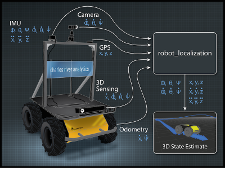
When incorporating sensor data into the position estimate of any of robot_localization’s state estimation nodes, it is important to extract as much information as possible. This tutorial details the best practices for sensor integration.
For additional information, users are encouraged to watch this presentation from ROSCon 2015.
Sensor Configuration
The configuration vector format is the same for all sensors, even if the message type in question doesn’t contain some of the variables in the configuration vector (e.g., a <<MsgLink(geometry_msgs/TwistWithCovarianceStamped)>> lacks any pose data, but the configuration vector still has values for pose variables). Unused variables are simply ignored.
Note that the configuration vector is given in the frame_id of the input message. For example, consider a velocity sensor that produces a geometry_msgs/TwistWithCovarianceStamped message with a frame_id of velocity_sensor_frame. In this example, we’ll assume that a transform exists from velocity_sensor_frame to your robot’s base_link_frame (e.g., base_link), and that the transform would convert \(X\) velocity in the velocity_sensor_frame to \(Z\) velocity in the base_link_frame. To include the \(X\) velocity data from the sensor into the filter, the configuration vector should set the \(X\) velocity value to true, and not the \(\dot{Z}\) velocity value:
<rosparam param="twist0_config">[false, false, false,
                                 false, false, false,
                                 true,  false, false,
                                 false, false, false,
                                 false, false, false]</rosparam>
Note
The order of the boolean values are \((X, Y, Z, roll, pitch, yaw, \dot{X}, \dot{Y}, \dot{Z}, \dot{roll}, \dot{pitch}, \dot{yaw}, \ddot{X}, \ddot{Y}, \ddot{Z})\).
Operating in 2D?
The first decision to make when configuring your sensors is whether or not your robot is operating in a planar environment, and you’re comfortable with ignoring subtle effects of variations in the ground plane as might be reported from an IMU. If so, please set the two_d_mode parameter to true. This effectively zeros out the 3D pose variables in every measurement and forces them to be fused in the state estimate.
Fusing Unmeasured Variables
Let’s start with an example. Let’s say you have a wheeled, nonholonomic robot that works in a planar environment. Your robot has some wheel encoders that are used to estimate instantaneous X velocity as well as absolute pose information. This information is reported in an nav_msgs/Odometry message. Additionally, your robot has an IMU that measures rotational velocity, vehicle attitude, and linear acceleration. Its data is reported in a sensor_msgs/Imu message. As we are operating in a planar environment, we set the two_d_mode parameter to true. This will automatically zero out all 3D variables, such as \(Z\), \(roll\), \(pitch\), their respective velocities, and \(Z\) acceleration. We start with this configuration:
<rosparam param="odom0_config">[true, true, false,
                                false, false, true,
                                true, false, false,
                                false, false, true,
                                false, false, false]</rosparam>

<rosparam param="imu0_config">[false, false, false,
                               false, false, true,
                               false, false, false,
                               false, false, true,
                               true, false, false]</rosparam>
As a first pass, this makes sense, as a planar robot only needs to concern itself with \(X\), \(Y\), \(\dot{X}\), \(\dot{Y}\), \(\ddot{X}\), \(\ddot{Y}\), \(yaw\), and \(\dot{yaw}\). However, there are a few things to note here.
- For
odom0, we are including \(X\) and \(Y\) (reported in a world coordinate frame), \(yaw\), \(\dot{X}\) (reported in the body frame), and \(\dot{yaw}\). However, unless your robot is internally using an IMU, it is most likely simply using wheel encoder data to generate the values in its measurements. Therefore, its velocity, heading, and position data are all generated from the same source. In that instance, we don’t want to use all the values, as you’re feeding duplicate information into the filter. Instead, it’s best to just use the velocities:
<rosparam param="odom0_config">[false, false, false,
                                false, false, false,
                                true, false, false,
                                false, false, true,
                                false, false, false]</rosparam>

<rosparam param="imu0_config">[false, false, false,
                               false, false, true,
                               false, false, false,
                               false, false, true,
                               true, false, false]</rosparam>
- Next, we note that we are not fusing \(\dot{Y}\). At first glance, this is the right choice, as our robot cannot move instantaneously sideways. However, if the nav_msgs/Odometry message reports a \(0\) value for \(\dot{Y}\) (and the \(\dot{Y}\) covariance is NOT inflated to a large value), it’s best to feed that value to the filter. As a \(0\) measurement in this case indicates that the robot cannot ever move in that direction, it serves as a perfectly valid measurement:
<rosparam param="odom0_config">[false, false, false,
                                false, false, false,
                                true, true, false,
                                false, false, true,
                                false, false, false]</rosparam>

<rosparam param="imu0_config">[false, false, false,
                               false, false, true,
                               false, false, false,
                               false, false, true,
                               true, false, false]</rosparam>
You may wonder why did we not fuse \(\dot{Z}\) velocity for the same reason. The answer is that we did when we set two_d_mode to false. If we hadn’t, we could, in fact, fuse the \(0\) measurement for \(\dot{Z}\) velocity into the filter.
- Last, we come to the IMU. You may notice that we have set the \(\ddot{Y}\) to false. This is due to the fact that many systems, including the hypothetical one we are discussing here, will not undergo instantaneous \(Y\) acceleration. However, the IMU will likely report non-zero, noisy values for Y acceleration, which can cause your estimate to drift rapidly.
The differential and relative Parameters
The state estimation nodes in ‘’robot_localization’’ allow users to fuse as many sensors as they like. This allows users to measure certain state vector variables - in particular, pose variables - using more than one source. For example, your robot may obtain absolute orientation information from multiple IMUs, or it may have multiple data sources providing an estimate its absolute position. In this case, users have two options:
- Fuse all the absolute position/orientation data as-is, e.g.,
<rosparam param="imu0_config">[false, false, false,
                               true,  true,  true,
                               false, false, false,
                               false, false, false,
                               false, false, false]</rosparam>

<rosparam param="imu1_config">[false, false, false,
                               true,  true,  true,
                               false, false, false,
                               false, false, false,
                               false, false, false]</rosparam>

In this case, users should be **very** careful and ensure that the covariances on each measured orientation variable are set correctly. If each IMU advertises a yaw variance of, for example, :math:`0.1`, yet the delta between the IMUs' yaw measurements is :math:`> 0.1`, then the output of the filter will oscillate back and forth between the values provided by each sensor. Users should make sure that the noise distributions around each measurement overlap.
- Alternatively, users can make use of the
_differentialparameter. By setting this to true for a given sensor, all pose (position and orientation) data is converted to a velocity by calculating the change in the measurement value between two consecutive time steps. The data is then fused as a velocity. Again, though, users should take care: when measurements are fused absolutely (especially IMUs), if the measurement has a static or non-increasing variance for a given variable, then the variance in the estimate’s covariance matrix will be bounded. If that information is converted to a velocity, then at each time step, the estimate will gain some small amount of error, and the variance for the variable in question will grow without bound. For position \((X, Y, Z)\) information, this isn’t an issue, but for orientation data, it is a problem. For example, it is acceptable for a robot to move around its environment and accumulate \(1.5\) meters of error in the \(X\) direction after some time. If that same robot moves around and accumulates \(1.5\) radians of error in yaw, then when the robot next drives forward, its position error will explode.
The general rule of thumb for the _differential parameter is that if a give robot has only one source of orientation data, then the differential parameter should be set to false. If there are \(N\) sources, users can set the _differential parameter to true for \(N-1\) of them, or simply ensure that the covariance values are large enough to eliminate oscillations.