The following diagram shows the overall architecture of the PSENscan software.
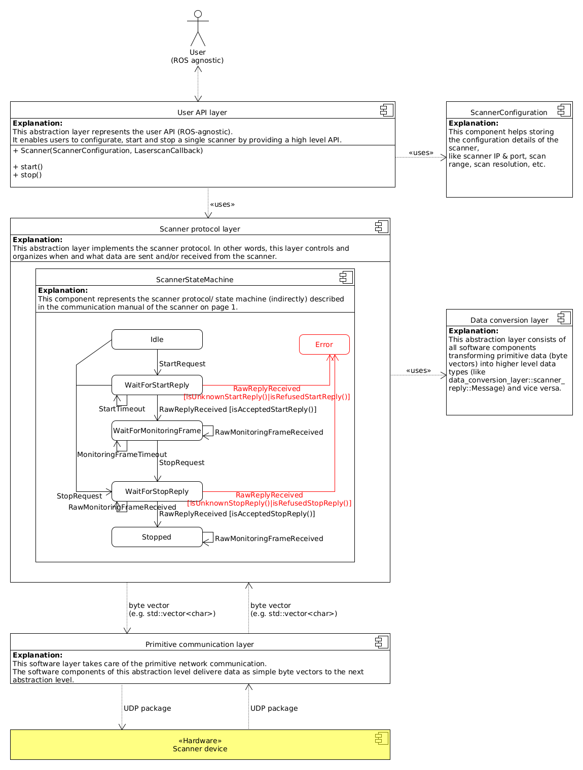
Diagram showing the high level overall architecture of the system
Detailed Description
The overall architecture should give a good idea of how the driver is supposed to work. For more details we recommend taking a look at the source code itself:
- For the ROS part we refer to
psen_scan_v2::ROSScannerNodeT. - The referenced User API is implemented by
psen_scan_v2_standalone::ScannerV2. - For the Scanner protocol layer please check
psen_scan_v2_standalone::protocol_layer::ScannerStateMachine. - Data Serialization and Deserialization is for example handled in
psen_scan_v2_standalone::data_conversion_layer::monitoring_frame::deserialize()orpsen_scan_v2_standalone::data_conversion_layer::scanner_reply::serialize(). - For the Primitive communication layer we recommend taking a look at
psen_scan_v2_standalone::communication_layer::UdpClientImpl.
Workflow
To help understand the workflow the following sequence diagram shows the interaction between the software components in a typical use case scenario (User calls start, receives a laserscan and calls stop).
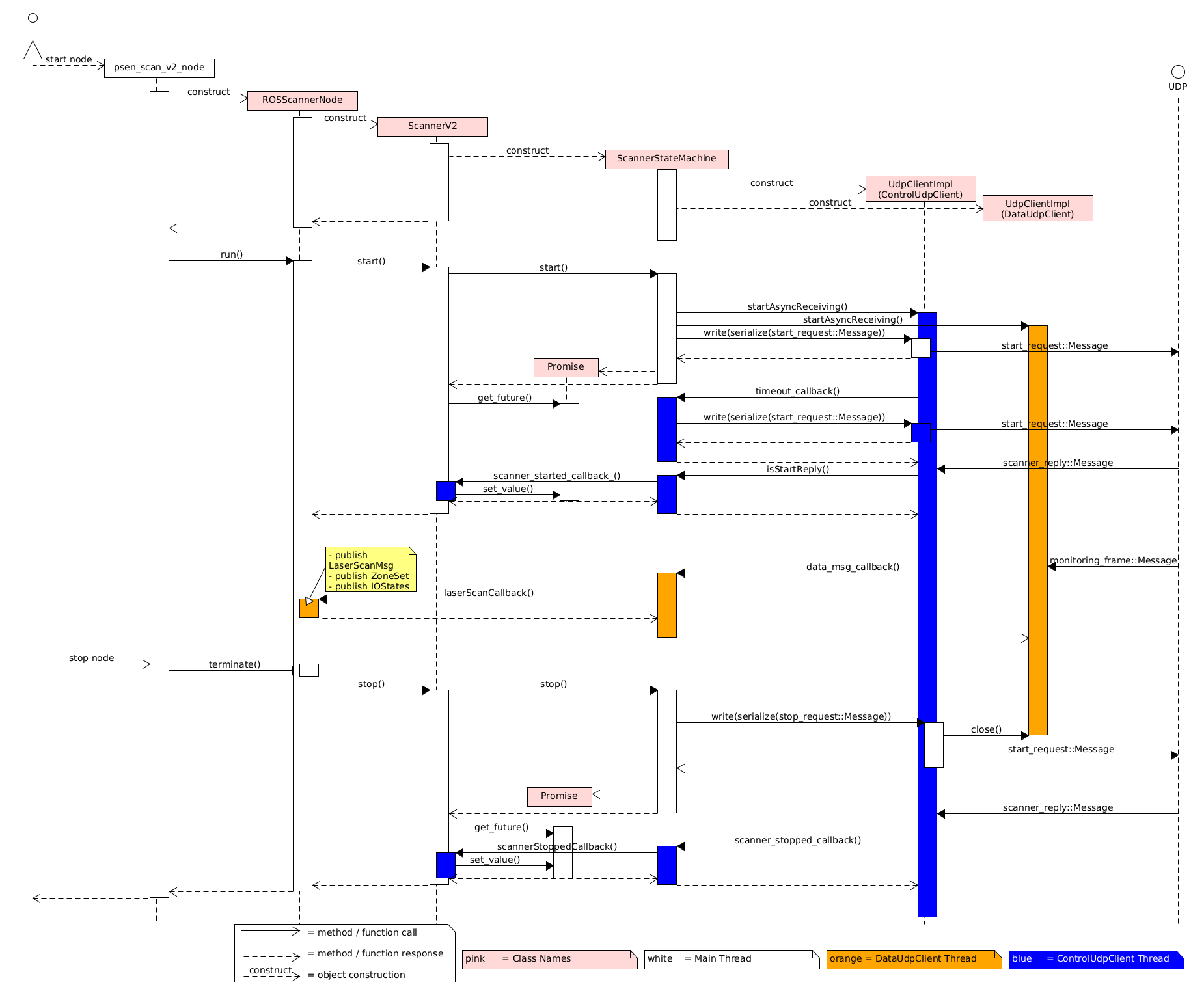
Sequence diagram showing the interaction between the software components