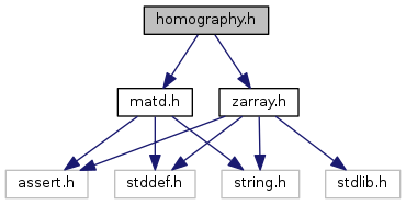
Go to the source code of this file.
Macros | |
| #define | HOMOGRAPHY_COMPUTE_FLAG_INVERSE 1 |
| #define | HOMOGRAPHY_COMPUTE_FLAG_SVD 0 |
Functions | |
| matd_t * | homography_compute (zarray_t *correspondences, int flags) |
| static void | homography_project (const matd_t *H, double x, double y, double *ox, double *oy) |
| matd_t * | homography_to_model_view (const matd_t *H, double F, double G, double A, double B, double C, double D) |
| matd_t * | homography_to_pose (const matd_t *H, double fx, double fy, double cx, double cy) |
Macro Definition Documentation
| #define HOMOGRAPHY_COMPUTE_FLAG_INVERSE 1 |
Given a 3x3 homography matrix and the focal lengths of the camera, compute the pose of the tag. The focal lengths should be given in pixels. For example, if the camera's focal length is twice the width of the sensor, and the sensor is 600 pixels across, the focal length in pixels is 2*600. Note that the focal lengths in the fx and fy direction will be approximately equal for most lenses, and is not a function of aspect ratio.
Theory: The homography matrix is the product of the camera projection matrix and the tag's pose matrix (the matrix that projects points from the tag's local coordinate system to the camera's coordinate frame).
[ h00 h01 h02 h03] = [ fx 0 cx 0 ] [ R00 R01 R02 TX ] [ h10 h11 h12 h13] = [ 0 fy cy 0 ] [ R10 R11 R12 TY ] [ h20 h21 h22 h23] = [ 0 0 s 0 ] [ R20 R21 R22 TZ ] [ 0 0 0 1 ]
fx is the focal length in the x direction of the camera (typically measured in pixels), fy is the focal length. cx and cy give the focal center (usually the middle of the image), and s is either +1 or -1, depending on the conventions you use. (We use 1.)
When observing a tag, the points we project in world space all have z=0, so we can form a 3x3 matrix by eliminating the 3rd column of the pose matrix.
[ h00 h01 h02 ] = [ fx 0 cx 0 ] [ R00 R01 TX ] [ h10 h11 h12 ] = [ 0 fy cy 0 ] [ R10 R11 TY ] [ h20 h21 h22 ] = [ 0 0 s 0 ] [ R20 R21 TZ ] [ 0 0 1 ]
(note that these h's are different from the ones above.)
We can multiply the right-hand side to yield a set of equations relating the values of h to the values of the pose matrix.
There are two wrinkles. The first is that the homography matrix is known only up to scale. We recover the unknown scale by constraining the magnitude of the first two columns of the pose matrix to be 1. We use the geometric average scale. The sign of the scale factor is recovered by constraining the observed tag to be in front of the camera. Once scaled, we recover the first two colmuns of the rotation matrix. The third column is the cross product of these.
The second wrinkle is that the computed rotation matrix might not be exactly orthogonal, so we perform a polar decomposition to find a good pure rotation approximation.
Tagsize is the size of the tag in your desired units. I.e., if your tag measures 0.25m along the side, your tag size is 0.25. (The homography is computed in terms of half the tag size, i.e., that a tag is 2 units wide as it spans from -1 to +1, but this code makes the appropriate adjustment.)
A note on signs:
The code below incorporates no additional negative signs, but respects the sign of any parameters that you pass in. Flipping the signs allows you to modify the projection to suit a wide variety of conditions.
In the "pure geometry" projection matrix, the image appears upside down; i.e., the x and y coordinates on the left hand side are the opposite of those on the right of the camera projection matrix. This would happen for all parameters positive: recall that points in front of the camera have negative Z values, which will cause the sign of all points to flip.
However, most cameras flip things so that the image appears "right side up" as though you were looking through the lens directly. This means that the projected points should have the same sign as the points on the right of the camera projection matrix. To achieve this, flip fx and fy.
One further complication: cameras typically put y=0 at the top of the image, instead of the bottom. Thus you generally want to flip y yet again (so it's now positive again).
General advice: you probably want fx negative, fy positive, cx and cy positive, and s=1.
Definition at line 134 of file homography.h.
| #define HOMOGRAPHY_COMPUTE_FLAG_SVD 0 |
Definition at line 135 of file homography.h.
Function Documentation
Definition at line 43 of file homography.c.
|
inlinestatic |
Definition at line 140 of file homography.h.
| matd_t* homography_to_model_view | ( | const matd_t * | H, |
| double | F, | ||
| double | G, | ||
| double | A, | ||
| double | B, | ||
| double | C, | ||
| double | D | ||
| ) |
Definition at line 366 of file homography.c.
Definition at line 281 of file homography.c.