Class for constraints on the visibility relationship between a sensor and a target. More...
#include <kinematic_constraint.h>
Public Member Functions | |
| virtual void | clear () |
| Clear the stored constraint. | |
| bool | configure (const moveit_msgs::VisibilityConstraint &vc, const robot_state::Transforms &tf) |
| Configure the constraint based on a moveit_msgs::VisibilityConstraint. | |
| virtual ConstraintEvaluationResult | decide (const robot_state::RobotState &state, bool verbose=false) const |
| Decide whether the constraint is satisfied in the indicated state. | |
| virtual bool | enabled () const |
| This function returns true if this constraint is configured and able to decide whether states do meet the constraint or not. If this function returns false it means that decide() will always return true -- there is no constraint to be checked. | |
| virtual bool | equal (const KinematicConstraint &other, double margin) const |
| Check if two constraints are the same. | |
| void | getMarkers (const robot_state::RobotState &state, visualization_msgs::MarkerArray &markers) const |
| Adds markers associated with the visibility cone, sensor and target to the visualization array. | |
| shapes::Mesh * | getVisibilityCone (const robot_state::RobotState &state) const |
| Gets a trimesh shape representing the visibility cone. | |
| virtual void | print (std::ostream &out=std::cout) const |
| Print the constraint data. | |
| VisibilityConstraint (const robot_model::RobotModelConstPtr &model) | |
| Constructor. | |
Protected Member Functions | |
| bool | decideContact (const collision_detection::Contact &contact) const |
| Function that gets passed into collision checking to allow some collisions. | |
Protected Attributes | |
| collision_detection::CollisionRobotPtr | collision_robot_ |
| A copy of the collision robot maintained for collision checking the cone against robot links. | |
| unsigned int | cone_sides_ |
| Storage for the cone sides. | |
| double | max_range_angle_ |
| Storage for the max range angle. | |
| double | max_view_angle_ |
| Storage for the max view angle. | |
| bool | mobile_sensor_frame_ |
| True if the sensor is a non-fixed frame relative to the transform frame. | |
| bool | mobile_target_frame_ |
| True if the target is a non-fixed frame relative to the transform frame. | |
| EigenSTL::vector_Vector3d | points_ |
| A set of points along the base of the circle. | |
| std::string | sensor_frame_id_ |
| The sensor frame id. | |
| Eigen::Affine3d | sensor_pose_ |
| The sensor pose transformed into the transform frame. | |
| int | sensor_view_direction_ |
| Storage for the sensor view direction. | |
| std::string | target_frame_id_ |
| The target frame id. | |
| Eigen::Affine3d | target_pose_ |
| The target pose transformed into the transform frame. | |
| double | target_radius_ |
| Storage for the target radius. | |
Detailed Description
Class for constraints on the visibility relationship between a sensor and a target.
Visibility constraints are the most complicated kinematic constraint type. They are designed to test whether a visibility relationship is maintained in a given state. For the visibility relationship to be maintained, a sensor must have an unimpeded view of a target - this is useful, for instance, if one wants to test whether a robot can see its hand with a given sensor in a given state. The mechanism that is used to test the constraint is a combination of geometric checks, and then a collision check that tests whether a cone that connects the sensor and the target is entirely unobstructed by the robot's links.
The constraint consists of a sensor pose, a target pose, a few parameters that govern the shape of the target, and a few parameters that allow finer control over the geometry of the check. There are two general ways that this constraint can be used. The first way to leave max_view_angle and max_range_angle in the VisibilityConstraint message as 0.0. In this case, the only check that is performed is the collision check against the cone. This check assumes that the sensor can see in all directions - the orientation of the sensor has no effect on the creation of the cone. It is important to note that the sensor and the target poses must not result in collision - if they are associated with sensor frames or robot links they must be specified to be outside the robot's body or all states will violate the Visibility Constraint. For an example of a visualization of a visibility constraint (produced using the getMarkers member function), see this image:
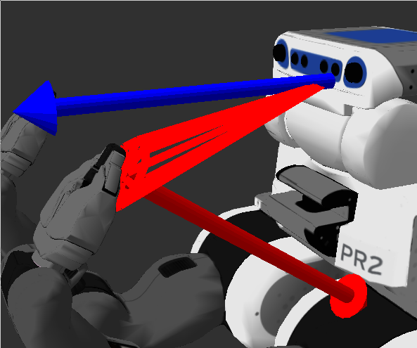
The cone is shown in red, and the arrows show normals. This visibility constraint uses a sensor pose (the narrow end of the cone ) of the PR2's narrow_stereo_optical_frame, except shifted along the Z axis such that the pose is outside of the robot's head and doesn't collide. The cone is allowed to collide with the actual sensor associated with the header frame, just not with any other links. The target pose is a 5 cm circle offset from the l_gripper_r_finger_tip_link, again so as not to collide - again, the cone can collide with the target link, but now with any other links. In the indicated state the cone is collision free and thus satisfies the collision component of the visibility constraint. In this image, however, the right arm intersects the cone, violating the visibility constraint:
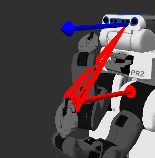
Note that both the target and the sensor frame can change with the robot's state.
The collision check essentially asks whether or not the volume between the sensor pose and the target pose are clear, but that's only one aspect of visibility we may care about. The visibility constraint also allows for some geometric reasoning about the relationship between the sensor or the target - this allows information such as approximate field of view of the sensor to be factored into the constraint. To use this reasoning, the sensor_view_direction of the field should first be set - this specifies which axis of the sensor pose frame is actually pointing. The system assumes that the the sensor pose has been set up such that a single of the axes is pointing directly out of the sensor. Once this value is set correctly, one or both of the max_view_angle and the max_range_angle values can be set. Setting a positive max_view_angle will constrain the sensor along the specified axis and the target along its Z axis to be pointing at each other. Practically speaking, this ensures that the sensor has sufficient visibility to the front of the target - if the target is pointing the opposite direction, or is too steeply perpindicular to the target, then the max_view_angle part of the constraint will be violated. The getMarkers function can again help explain this - the view angle is the angular difference between the blue arrow associated with the sensor and the red arrow associated with the target.
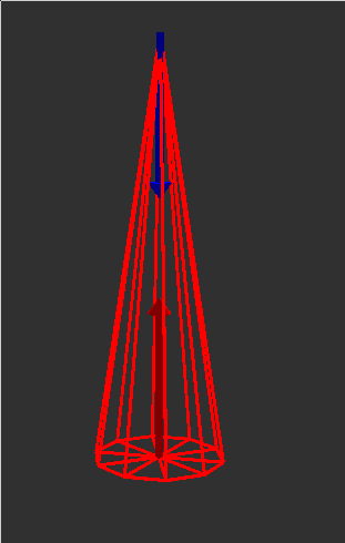
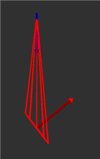
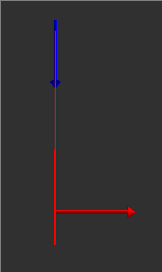
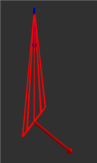
If constraining the target to be within the field of view of the sensor is the goal, then the max_range_angle can be set. The range angle is calculated as the angle between the origins of the sensor and the target frame - the orientations are unimportant. In the above images, the range angle is always 0, as the target's center is directly lined up with the blue arrow. In this image, however, the view angle is evaluated at 0.0, while the range angle is evaluated at .65.
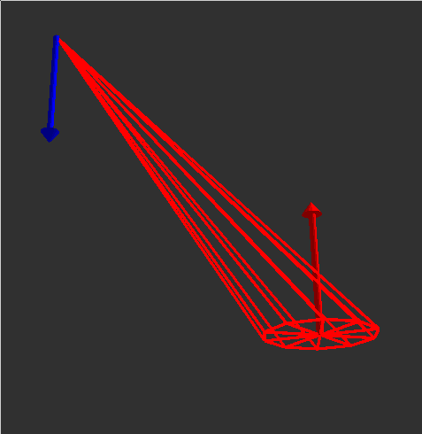
By limiting the max_range_angle, you can constrain the target to be within the field of view of the sensor. Max_view_angle and max_range_angle can be used at once.
Definition at line 749 of file kinematic_constraint.h.
Constructor & Destructor Documentation
| kinematic_constraints::VisibilityConstraint::VisibilityConstraint | ( | const robot_model::RobotModelConstPtr & | model | ) |
Constructor.
- Parameters:
-
[in] model The kinematic model used for constraint evaluation
Definition at line 648 of file kinematic_constraint.cpp.
Member Function Documentation
| void kinematic_constraints::VisibilityConstraint::clear | ( | ) | [virtual] |
Clear the stored constraint.
Implements kinematic_constraints::KinematicConstraint.
Definition at line 654 of file kinematic_constraint.cpp.
| bool kinematic_constraints::VisibilityConstraint::configure | ( | const moveit_msgs::VisibilityConstraint & | vc, |
| const robot_state::Transforms & | tf | ||
| ) |
Configure the constraint based on a moveit_msgs::VisibilityConstraint.
For the configure command to be successful, the target radius must be non-zero (negative values will have the absolute value taken). If cone sides are less than 3, a value of 3 will be used.
- Parameters:
-
[in] vc moveit_msgs::VisibilityConstraint for configuration
- Returns:
- True if constraint can be configured from vc
Definition at line 670 of file kinematic_constraint.cpp.
| kinematic_constraints::ConstraintEvaluationResult kinematic_constraints::VisibilityConstraint::decide | ( | const robot_state::RobotState & | state, |
| bool | verbose = false |
||
| ) | const [virtual] |
Decide whether the constraint is satisfied in the indicated state.
- Parameters:
-
[in] state The kinematic state used for evaluation [in] verbose Whether or not to print output
- Returns:
Implements kinematic_constraints::KinematicConstraint.
Definition at line 917 of file kinematic_constraint.cpp.
| bool kinematic_constraints::VisibilityConstraint::decideContact | ( | const collision_detection::Contact & | contact | ) | const [protected] |
Function that gets passed into collision checking to allow some collisions.
The cone object is allowed to touch either the sensor or the header frame, but not anything else
- Parameters:
-
[in] contact The contact in question
- Returns:
- True if the collision is allowed, otherwise false
Definition at line 997 of file kinematic_constraint.cpp.
| bool kinematic_constraints::VisibilityConstraint::enabled | ( | ) | const [virtual] |
This function returns true if this constraint is configured and able to decide whether states do meet the constraint or not. If this function returns false it means that decide() will always return true -- there is no constraint to be checked.
Implements kinematic_constraints::KinematicConstraint.
Definition at line 771 of file kinematic_constraint.cpp.
| bool kinematic_constraints::VisibilityConstraint::equal | ( | const KinematicConstraint & | other, |
| double | margin | ||
| ) | const [virtual] |
Check if two constraints are the same.
For visibility constraints this means that:
- The types are the same,
- The target frame ids are the same
- The sensor frame ids are the same
- The cone sides number is the same
- The sensor view directions are the same
- The max view angles and target radii are within the margin
- The sensor and target poses are within the margin, as computed by taking the norm of the difference.
- Parameters:
-
[in] other The other constraint to test [in] margin The margin to apply to all values associated with constraint
- Returns:
- True if equal, otherwise false
Implements kinematic_constraints::KinematicConstraint.
Definition at line 743 of file kinematic_constraint.cpp.
| void kinematic_constraints::VisibilityConstraint::getMarkers | ( | const robot_state::RobotState & | state, |
| visualization_msgs::MarkerArray & | markers | ||
| ) | const |
Adds markers associated with the visibility cone, sensor and target to the visualization array.
The visibility cone and two arrows - a blue array that issues from the sensor_view_direction of the sensor, and a red arrow the issues along the Z axis of the the target frame.
- Parameters:
-
[in] state The state from which to produce the markers [out] markers The marker array to which the markers will be added
Definition at line 848 of file kinematic_constraint.cpp.
| shapes::Mesh * kinematic_constraints::VisibilityConstraint::getVisibilityCone | ( | const robot_state::RobotState & | state | ) | const |
Gets a trimesh shape representing the visibility cone.
- Parameters:
-
[in] state The state from which to produce the cone
- Returns:
- The shape associated with the cone
Definition at line 776 of file kinematic_constraint.cpp.
| void kinematic_constraints::VisibilityConstraint::print | ( | std::ostream & | out = std::cout | ) | const [virtual] |
Print the constraint data.
- Parameters:
-
[in] out The file descriptor for printing
Reimplemented from kinematic_constraints::KinematicConstraint.
Definition at line 1021 of file kinematic_constraint.cpp.
Member Data Documentation
collision_detection::CollisionRobotPtr kinematic_constraints::VisibilityConstraint::collision_robot_ [protected] |
A copy of the collision robot maintained for collision checking the cone against robot links.
Definition at line 835 of file kinematic_constraint.h.
unsigned int kinematic_constraints::VisibilityConstraint::cone_sides_ [protected] |
Storage for the cone sides.
Definition at line 843 of file kinematic_constraint.h.
double kinematic_constraints::VisibilityConstraint::max_range_angle_ [protected] |
Storage for the max range angle.
Definition at line 847 of file kinematic_constraint.h.
double kinematic_constraints::VisibilityConstraint::max_view_angle_ [protected] |
Storage for the max view angle.
Definition at line 846 of file kinematic_constraint.h.
bool kinematic_constraints::VisibilityConstraint::mobile_sensor_frame_ [protected] |
True if the sensor is a non-fixed frame relative to the transform frame.
Definition at line 836 of file kinematic_constraint.h.
bool kinematic_constraints::VisibilityConstraint::mobile_target_frame_ [protected] |
True if the target is a non-fixed frame relative to the transform frame.
Definition at line 837 of file kinematic_constraint.h.
A set of points along the base of the circle.
Definition at line 844 of file kinematic_constraint.h.
std::string kinematic_constraints::VisibilityConstraint::sensor_frame_id_ [protected] |
The sensor frame id.
Definition at line 839 of file kinematic_constraint.h.
Eigen::Affine3d kinematic_constraints::VisibilityConstraint::sensor_pose_ [protected] |
The sensor pose transformed into the transform frame.
Definition at line 840 of file kinematic_constraint.h.
Storage for the sensor view direction.
Definition at line 841 of file kinematic_constraint.h.
std::string kinematic_constraints::VisibilityConstraint::target_frame_id_ [protected] |
The target frame id.
Definition at line 838 of file kinematic_constraint.h.
Eigen::Affine3d kinematic_constraints::VisibilityConstraint::target_pose_ [protected] |
The target pose transformed into the transform frame.
Definition at line 842 of file kinematic_constraint.h.
double kinematic_constraints::VisibilityConstraint::target_radius_ [protected] |
Storage for the target radius.
Definition at line 845 of file kinematic_constraint.h.
The documentation for this class was generated from the following files: