Integrating GPS Data
Integration of GPS data is a common request from users. robot_localization contains a node, navsat_transform_node, that transforms GPS data into a frame that is consistent with your robot’s starting pose (position and orientation) in its world frame. This greatly simplifies fusion of GPS data. This tutorial explains how to use navsat_transform_node, and delves into some of the math behind it.
For additional information, users are encouraged to watch this presentation from ROSCon 2015.
Notes on Fusing GPS Data
Before beginning this tutorial, users should be sure to familiarize themselves with REP-105. It is important for users to realize that using a position estimate that includes GPS data will likely be unfit for use by navigation modules, owing to the fact that GPS data is subject to discrete discontinuities (“jumps”). If you want to fuse data from a GPS into your position estimate, one potential solution is to do the following:
- Run one instance of a
robot_localizationstate estimation node that fuses only continuous data, such as odometry and IMU data. Set theworld_frameparameter for this instance to the same value as theodom_frameparameter. Execute local path plans and motions in this frame. - Run another instance of a
robot_localizationstate estimation node that fuses all sources of data, including the GPS. Set theworld_frameparameter for this instance to the same value as themap_frameparameter.
This is just a suggestion, however, and users are free to fuse the GPS data into a single instance of a robot_localization state estimation node.
Using navsat_transform_node
The diagram below illustrates an example setup:
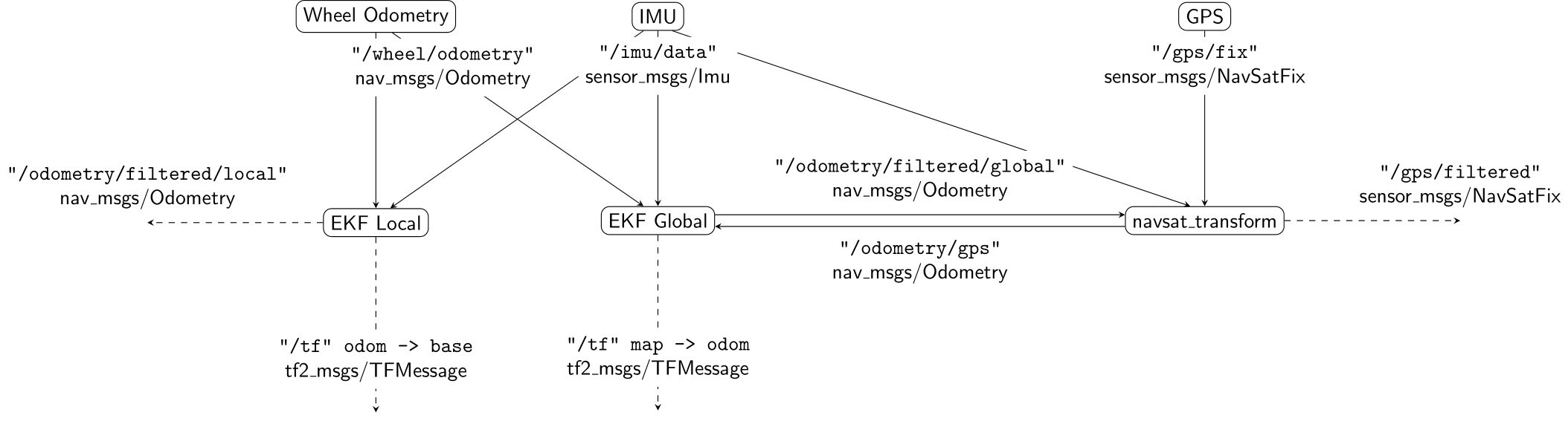
Required Inputs
navsat_transform_node requires three sources of information: the robot’s current pose estimate in its world frame, an earth-referenced heading, and a geographic coordinate expressed as a latitude/longitude pair (with optional altitude).
These data can be obtained in three different ways:
- (Default behavior) The data can come entirely from the robot’s sensors and pose estimation software. To enable this mode, make sure the
wait_for_datumparameter is set to false (its default value). The required messages are:
- A sensor_msgs/NavSatFix message with raw GPS coordinates in it.
- A sensor_msgs/Imu message with an absolute (earth-referenced) heading.
- A nav_msgs/Odometry message that contains the robot’s current position estimate in the frame specified by its start location (typically the output of a
robot_localizationstate estimation node).
- The datum (global frame origin) can be specified via the
datumparameter.
Note
In order to use this mode, the
wait_for_datumparameter must be set to true.The
datumparameter takes this form:<rosparam param="datum">[55.944904, -3.186693, 0.0, map, base_link]</rosparam>The parameter order is
latitudein decimal degrees,longitudein decimal degrees,headingin radians) theframe_idof your robot’s world frame (i.e., the value of theworld_frameparameter in arobot_localizationstate estimation node), and theframe_idof your robot’s body frame (i.e., the value of thebase_link_frameparameter in arobot_localizationstate estimation node). When this mode is used, the robot assumes that your robot’s world frame origin is at the specified latitude and longitude and with a heading of \(0\) (east).
- The datum can be set manually via the
set_datumservice and using the robot_localization/SetDatum service message.
GPS Data
Please note that all development of navsat_transform_node was done using a Garmin 18x GPS unit, so there may be intricacies of the data generated by other units that need to be handled.
The excellent nmea_navsat_driver package provides the required sensor_msgs/NavSatFix message. Here is the nmea_navsat_driver launch file we’ll use for this tutorial:
<node pkg="nmea_navsat_driver" type="nmea_serial_driver" name="navsat" respawn="true">
  <param name="port" value="/dev/ttyUSB0"/>
  <param name="baud" value="19200"/>
</node>
This information is only relevant if the user is not manually specifying the origin via the datum parameter or the set_datum service.
IMU Data
Note
Since version 2.2.1, navsat_transform_node has moved to a standard wherein all heading data is assumed to start with its zero point facing east. If your IMU does not conform to this standard and instead reports zero when facing north, you can still use the yaw_offset parameter to correct this. In this case, the value for yaw_offset would be \(\pi / 2\) (approximately \(1.5707963\)).
Users should make sure their IMUs conform to REP-105. In particular, check that the signs of your orientation angles increase in the right direction. In addition, users should look up the magnetic declination for their robot’s operating area, convert it to radians, and then use that value for the magnetic_declination_radians parameter.
This information is only relevant if the user is not manually specifying the origin via the datum parameter or the set_datum service.
Odometry Data
This should just be the output of whichever robot_localization state estimation node instance you are using to fuse GPS data.
Configuring robot_localization
Integration with robot_localization is straightforward at this point. Simply add this block to your state estimation node launch file:
<param name="odomN" value="/your_state_estimation_node_topic">

<rosparam param="odomN_config">[true,  true,  false,
                                false, false, false,
                                false, false, false,
                                false, false, false,
                                false, false, false]</rosparam>
<param name="odomN_differential" value="false"/>
Make sure to change odomN to whatever your odometry input values is (e.g., odom1, odom2, etc.). Also, if you wish to include altitude data, set odomN_config’s third value to true.
Note
If you are operating in 2D don’t have any sensor measuring Z or Z velocity, you can either:
- Set
navsat_transform_node'szero_altitudeparameter to true, and then setodomN_config’s third value to true - Set
two_d_modeto true in yourrobot_localizationstate estimation node
You should have no need to modify the _differential setting within the state estimation node. The GPS is an absolute position sensor, and enabling differential integration defeats the purpose of using it.
Details
We’ll start with a picture. Consider a robot that starts at some latitude and longitude and with some heading. We assume in this tutorial that the heading comes from an IMU that reads 0 when facing east, and increases according to the ROS spec (i.e., counter-clockwise). The remainder of this tutorial will refer to Figure 2:
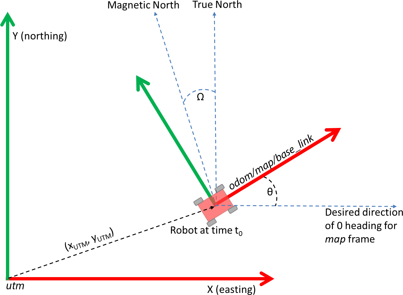
REP-105 suggests four coordinate frames: base_link, odom, map, and earth. base_link is the coordinate frame that is rigidly attached to the vehicle. The odom and map frames are world-fixed frames and generally have their origins at the vehicle’s start position and orientation. The earth frame is used as a common reference frame for multiple map frames, and is not yet supported by navsat_transform_node. Note that in Figure 2, the robot has just started (t = 0), and so its base_link, odom, and map frames are aligned. We can also define a coordinate frame for the UTM grid, which we will call utm. For the purposes of this tutorial, we will refer to the UTM grid coordinate frame as utm. Therefore, what we want to do is create a utm->*map* transform.
Referring to Figure 2, these ideas are (hopefully) made clear. The UTM origin is the \((0_{UTM}, 0_{UTM})\) point of the UTM zone that is associated with the robot’s GPS location. The robot begins somewhere within the UTM zone at location \((x_{UTM}, y_{UTM})\). The robot’s initial orientation is some angle \(\theta\) above the UTM grid’s \(X\)-axis. Our transform will therefore require that we know \(x_{UTM}, y_{UTM}\) and \(\theta\).
We now need to convert our latitude and longitude to UTM coordinates. The UTM grid assumes that the \(X\)-axis faces east, the \(Y\)-axis faces (true) north, and the \(Z\)-axis points up out of the ground. This complies with the right-handed coordinate frame as dictated by REP-105. The REP also states that a yaw angle of \(0\) means that we are facing straight down the \(X\)-axis, and that the yaw increases counter-clockwise. navsat_transform_node assumes your heading data conforms to this standard. However, there are two factors that need to be considered:
- The IMU driver may not allow the user to apply the magnetic declination correction factor
- The IMU driver may incorrectly report \(0\) when facing north, and not when facing east (even though its headings increase and decrease correctly). Fortunately,
navsat_transform_nodeexposes two parameters to adddress these possible shortcomings in IMU data:magnetic_declination_radiansandyaw_offset. Referring to Figure 2, for an IMU that is currently measuring a yaw value ofimu_yaw,
\(yaw_{imu} = -\omega - offset_{yaw} + \theta\)
\(\theta = yaw_{imu} + \omega + offset_{yaw}\)
We now have a translation \((x_{UTM}, y_{UTM})\) and rotation \(\theta\), which we can use to create the required utm -> map transform. We use the transform to convert all future GPS positions into the robot’s local coordinate frame. navsat_transform_node will also broadcast this transform if the broadcast_utm_transform parameter is set to true.
If you have any questions about this tutorial, please feel free to ask questions on answers.ros.org.