ImuDisplay
Overview
This tutorial shows how to write a simple Display plugin for RViz.
RViz does not currently have a way to display sensor_msgs/Imu messages directly. The code in this tutorial implements a subclass of rviz::Display to do so.
The source code for this tutorial is in the rviz_plugin_tutorials package. You can check out the source directly or (if you use Ubuntu) you can just apt-get install the pre-compiled Debian package like so:
sudo apt-get install ros-hydro-visualization-tutorials
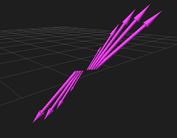
Here is what the new ImuDisplay output looks like, showing a sequence of sensor_msgs/Imu messages from the test script:
The Plugin Code
The code for ImuDisplay is in these files: src/imu_display.h, src/imu_display.cpp, src/imu_visual.h, and src/imu_visual.cpp.
imu_display.h
The full text of imu_display.h is here: src/imu_display.h
Here we declare our new subclass of rviz::Display. Every display which can be listed in the “Displays” panel is a subclass of rviz::Display.
ImuDisplay will show a 3D arrow showing the direction and magnitude of the IMU acceleration vector. The base of the arrow will be at the frame listed in the header of the Imu message, and the direction of the arrow will be relative to the orientation of that frame. It will also optionally show a history of recent acceleration vectors, which will be stored in a circular buffer.
The ImuDisplay class itself just implements the circular buffer, editable parameters, and Display subclass machinery. The visuals themselves are represented by a separate class, ImuVisual. The idiom for the visuals is that when the objects exist, they appear in the scene, and when they are deleted, they disappear.
class ImuDisplay: public rviz::MessageFilterDisplay<sensor_msgs::Imu>
{
Q_OBJECT
public:
Constructor. pluginlib::ClassLoader creates instances by calling the default constructor, so make sure you have one.
ImuDisplay();
virtual ~ImuDisplay();
Overrides of protected virtual functions from Display. As much as possible, when Displays are not enabled, they should not be subscribed to incoming data and should not show anything in the 3D view. These functions are where these connections are made and broken.
protected:
  virtual void onInitialize();
A helper to clear this display back to the initial state.
virtual void reset();
These Qt slots get connected to signals indicating changes in the user-editable properties.
private Q_SLOTS:
  void updateColorAndAlpha();
  void updateHistoryLength();
Function to handle an incoming ROS message.
private:
  void processMessage( const sensor_msgs::Imu::ConstPtr& msg );
Storage for the list of visuals. It is a circular buffer where data gets popped from the front (oldest) and pushed to the back (newest)
boost::circular_buffer<boost::shared_ptr<ImuVisual> > visuals_;
User-editable property variables.
  rviz::ColorProperty* color_property_;
  rviz::FloatProperty* alpha_property_;
  rviz::IntProperty* history_length_property_;
};
imu_display.cpp
The full text of imu_display.cpp is here: src/imu_display.cpp
The constructor must have no arguments, so we can’t give the constructor the parameters it needs to fully initialize.
ImuDisplay::ImuDisplay()
{
  color_property_ = new rviz::ColorProperty( "Color", QColor( 204, 51, 204 ),
                                             "Color to draw the acceleration arrows.",
                                             this, SLOT( updateColorAndAlpha() ));

  alpha_property_ = new rviz::FloatProperty( "Alpha", 1.0,
                                             "0 is fully transparent, 1.0 is fully opaque.",
                                             this, SLOT( updateColorAndAlpha() ));

  history_length_property_ = new rviz::IntProperty( "History Length", 1,
                                                    "Number of prior measurements to display.",
                                                    this, SLOT( updateHistoryLength() ));
  history_length_property_->setMin( 1 );
  history_length_property_->setMax( 100000 );
}
After the top-level rviz::Display::initialize() does its own setup, it calls the subclass’s onInitialize() function. This is where we instantiate all the workings of the class. We make sure to also call our immediate super-class’s onInitialize() function, since it does important stuff setting up the message filter.
Note that “MFDClass” is a typedef of
MessageFilterDisplay<message type>, to save typing that long
templated class name every time you need to refer to the
superclass.
void ImuDisplay::onInitialize()
{
  MFDClass::onInitialize();
  updateHistoryLength();
}

ImuDisplay::~ImuDisplay()
{
}
Clear the visuals by deleting their objects.
void ImuDisplay::reset()
{
  MFDClass::reset();
  visuals_.clear();
}
Set the current color and alpha values for each visual.
void ImuDisplay::updateColorAndAlpha()
{
  float alpha = alpha_property_->getFloat();
  Ogre::ColourValue color = color_property_->getOgreColor();

  for( size_t i = 0; i < visuals_.size(); i++ )
  {
    visuals_[ i ]->setColor( color.r, color.g, color.b, alpha );
  }
}
Set the number of past visuals to show.
void ImuDisplay::updateHistoryLength()
{
  visuals_.rset_capacity(history_length_property_->getInt());
}
This is our callback to handle an incoming message.
void ImuDisplay::processMessage( const sensor_msgs::Imu::ConstPtr& msg )
{
Here we call the rviz::FrameManager to get the transform from the fixed frame to the frame in the header of this Imu message. If it fails, we can’t do anything else so we return.
Ogre::Quaternion orientation;
Ogre::Vector3 position;
if( !context_->getFrameManager()->getTransform( msg->header.frame_id,
                                                msg->header.stamp,
                                                position, orientation ))
{
  ROS_DEBUG( "Error transforming from frame '%s' to frame '%s'",
             msg->header.frame_id.c_str(), qPrintable( fixed_frame_ ));
  return;
}
We are keeping a circular buffer of visual pointers. This gets the next one, or creates and stores it if the buffer is not full
boost::shared_ptr<ImuVisual> visual;
if( visuals_.full() )
{
  visual = visuals_.front();
}
else
{
  visual.reset(new ImuVisual( context_->getSceneManager(), scene_node_ ));
}
Now set or update the contents of the chosen visual.
visual->setMessage( msg );
visual->setFramePosition( position );
visual->setFrameOrientation( orientation );

float alpha = alpha_property_->getFloat();
Ogre::ColourValue color = color_property_->getOgreColor();
visual->setColor( color.r, color.g, color.b, alpha );
And send it to the end of the circular buffer
  visuals_.push_back(visual);
}

} // end namespace rviz_plugin_tutorials
Tell pluginlib about this class. It is important to do this in global scope, outside our package’s namespace.
#include <pluginlib/class_list_macros.h>
PLUGINLIB_EXPORT_CLASS(rviz_plugin_tutorials::ImuDisplay,rviz::Display )
imu_visual.h
The full text of imu_visual.h is here: src/imu_visual.h
Declare the visual class for this display.
Each instance of ImuVisual represents the visualization of a single sensor_msgs::Imu message. Currently it just shows an arrow with the direction and magnitude of the acceleration vector, but could easily be expanded to include more of the message data.
class ImuVisual
{
public:
Constructor. Creates the visual stuff and puts it into the scene, but in an unconfigured state.
ImuVisual( Ogre::SceneManager* scene_manager, Ogre::SceneNode* parent_node );
Destructor. Removes the visual stuff from the scene.
virtual ~ImuVisual();
Configure the visual to show the data in the message.
void setMessage( const sensor_msgs::Imu::ConstPtr& msg );
Set the pose of the coordinate frame the message refers to. These could be done inside setMessage(), but that would require calls to FrameManager and error handling inside setMessage(), which doesn’t seem as clean. This way ImuVisual is only responsible for visualization.
void setFramePosition( const Ogre::Vector3& position );
void setFrameOrientation( const Ogre::Quaternion& orientation );
Set the color and alpha of the visual, which are user-editable parameters and therefore don’t come from the Imu message.
  void setColor( float r, float g, float b, float a );

private:
The object implementing the actual arrow shape
boost::shared_ptr<rviz::Arrow> acceleration_arrow_;
A SceneNode whose pose is set to match the coordinate frame of the Imu message header.
Ogre::SceneNode* frame_node_;
The SceneManager, kept here only so the destructor can ask it to
destroy the frame_node_.
  Ogre::SceneManager* scene_manager_;
};
imu_visual.cpp
The full text of imu_visual.cpp is here: src/imu_visual.cpp
Ogre::SceneNode s form a tree, with each node storing the transform (position and orientation) of itself relative to its parent. Ogre does the math of combining those transforms when it is time to render.
Here we create a node to store the pose of the Imu’s header frame relative to the RViz fixed frame.
frame_node_ = parent_node->createChildSceneNode();
We create the arrow object within the frame node so that we can set its position and direction relative to its header frame.
  acceleration_arrow_.reset(new rviz::Arrow( scene_manager_, frame_node_ ));
}

ImuVisual::~ImuVisual()
{
Destroy the frame node since we don’t need it anymore.
  scene_manager_->destroySceneNode( frame_node_ );
}

void ImuVisual::setMessage( const sensor_msgs::Imu::ConstPtr& msg )
{
  const geometry_msgs::Vector3& a = msg->linear_acceleration;
Convert the geometry_msgs::Vector3 to an Ogre::Vector3.
Ogre::Vector3 acc( a.x, a.y, a.z );
Find the magnitude of the acceleration vector.
float length = acc.length();
Scale the arrow’s thickness in each dimension along with its length.
Ogre::Vector3 scale( length, length, length );
acceleration_arrow_->setScale( scale );
Set the orientation of the arrow to match the direction of the acceleration vector.
  acceleration_arrow_->setDirection( acc );
}
Position and orientation are passed through to the SceneNode.
void ImuVisual::setFramePosition( const Ogre::Vector3& position )
{
  frame_node_->setPosition( position );
}

void ImuVisual::setFrameOrientation( const Ogre::Quaternion& orientation )
{
  frame_node_->setOrientation( orientation );
}
Color is passed through to the Arrow object.
void ImuVisual::setColor( float r, float g, float b, float a )
{
  acceleration_arrow_->setColor( r, g, b, a );
}
Building the Plugin
To build the plugin, just do the normal “rosmake” thing:
rosmake rviz_plugin_tutorials
Exporting the Plugin
For the plugin to be found and understood by other ROS packages (in this case, rviz), it needs a “plugin_description.xml” file. This file can be named anything you like, as it is specified in the plugin package’s “package.xml” file like so:
<export>
    <rviz plugin="${prefix}/plugin_description.xml"/>
</export>
The contents of plugin_description.xml then look like this:
<library path="lib/librviz_plugin_tutorials">
  <class name="rviz_plugin_tutorials/Teleop"
         type="rviz_plugin_tutorials::TeleopPanel"
         base_class_type="rviz::Panel">
    <description>
      A panel widget allowing simple diff-drive style robot base control.
    </description>
  </class>
  <class name="rviz_plugin_tutorials/Imu"
         type="rviz_plugin_tutorials::ImuDisplay"
         base_class_type="rviz::Display">
    <description>
      Displays direction and scale of accelerations from sensor_msgs/Imu messages.
    </description>
    <message_type>sensor_msgs/Imu</message_type>
  </class>
  <class name="rviz_plugin_tutorials/PlantFlag"
         type="rviz_plugin_tutorials::PlantFlagTool"
         base_class_type="rviz::Tool">
    <description>
      Tool for planting flags on the ground plane in rviz.
    </description>
  </class>
</library>
The first line says that the compiled library lives in lib/librviz_plugin_tutorials (the ”.so” ending is appended by pluginlib according to the OS). This path is relative to the top directory of the package:
<library path="lib/librviz_plugin_tutorials">
The next section is a class entry describing the TeleopPanel:
<class name="rviz_plugin_tutorials/Teleop"
       type="rviz_plugin_tutorials::TeleopPanel"
       base_class_type="rviz::Panel">
  <description>
    A panel widget allowing simple diff-drive style robot base control.
  </description>
</class>
This specifies the name, type, base class, and description of the
class. The name field must be a combination of the first two
strings given to the PLUGINLIB_DECLARE_CLASS() macro in the source
file. It must be the “package” name, a “/” slash, then the “display
name” for the class. The “display name” is the name used for the
class in the user interface.
The type entry must be the fully-qualified class name, including any namespace(s) it is inside.
The base_class_type is usually one of rviz::Panel,
rviz::Display, rviz::Tool, or rviz::ViewController.
The description subsection is a simple text description of the
class, which is shown in the class-chooser dialog and in the Displays
panel help area. This section can contain HTML, including hyperlinks,
but the markup must be escaped to avoid being interpreted as XML
markup. For example a link tag might look like: <a
href="my-web-page.html">.
Display plugins can have multiple message_type tags, which are used by RViz when you add a Display by selecting it’s topic first.
Trying It Out
Once your RViz plugin is compiled and exported, simply run rviz normally:
rosrun rviz rviz
and rviz will use pluginlib to find all the plugins exported to it.
Add an ImuDisplay by clicking the “Add” button at the bottom of the “Displays” panel (or by typing Control-N), then scrolling down through the available displays until you see “Imu” under your plugin package name (here it is “rviz_plugin_tutorials”).
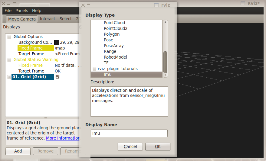
If “Imu” is not in your list of Display Types, look through RViz’s console output for error messages relating to plugin loading. Some common problems are:
- not having a plugin_description.xml file,
- not exporting it in the package.xml file, or
- not properly referencing the library file (like librviz_plugin_tutorials.so) from plugin_description.xml.
Once you’ve added the Imu display to RViz, you just need to set the topic name of the display to a source of sensor_msgs/Imu messages.
If you don’t happen to have an IMU or other source of sensor_msgs/Imu messages, you can test the plugin with a Python script like this: scripts/send_test_msgs.py.
The script publishes on the “/test_imu” topic, so enter that.
The script publishes both Imu messages and a moving TF frame (“/base_link” relative to “/map”), so make sure your “Fixed Frame” is set to “/map”.
Finally, adjust the “History Length” parameter of the Imu display to 10 and you should see something like the picture at the top of this page.
Note: If you use this to visualize messages from an actual IMU, the arrows are going to be huge compared to most robots:
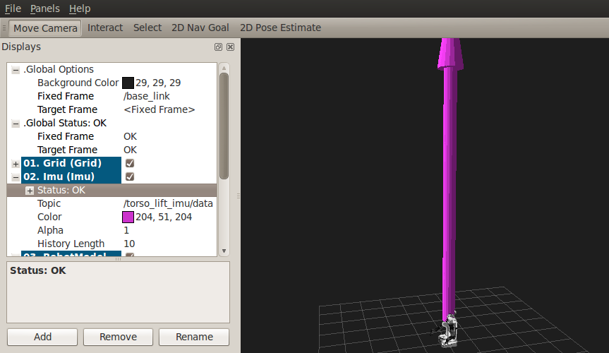
(Note the PR2 robot at the base of the purple arrow.) This is because the Imu acceleration units are meters per second squared, and gravity is 9.8 m/s^2, and we haven’t applied any scaling or gravity compensation to the acceleration vectors.
Next Steps
This ImuDisplay is not yet a terribly useful Display class. Extensions to make it more useful might be:
- Add a gravity-compensation option to the acceleration vector.
- Visualize more of the data in the Imu messages.
To add a gravity compensation option, you might take steps like these:
- Add a new
rviz::BoolPropertyto ImuDisplay to store whether the option is on or off. - Compute the direction of gravity relative to the Imu frame orientation (as set in ImuVisual::setFrameOrientation()) and subtract it from the acceleration vector each time in ImuVisual::setMessage().
Since ImuVisual takes complete Imu messages as input, adding visualizations of more of the Imu data only needs modifications to ImuVisual. Imu data displays might look like:
- orientation: An rviz::Axes object at the Imu reference frame, turned to show the orientation.
- angular_velocity: Maybe a line to show the axis of rotation and a 3D arrow curving around it to show the speed of rotation?
- orientation_covariance: Maybe this is an ellipse at the end of each of the X, Y, and Z axes showing the orientation?
- linear_acceleration_covariance: Maybe this is an ellipsoid at the end of the acceleration arrow?
As all this might be visually cluttered, it may make sense to include boolean options to enable or disable some of them.