Layer structure: multiScan136 vs. multiScan165
Summary table
Aspect |
multiScan136 |
multiScan165 |
|---|---|---|
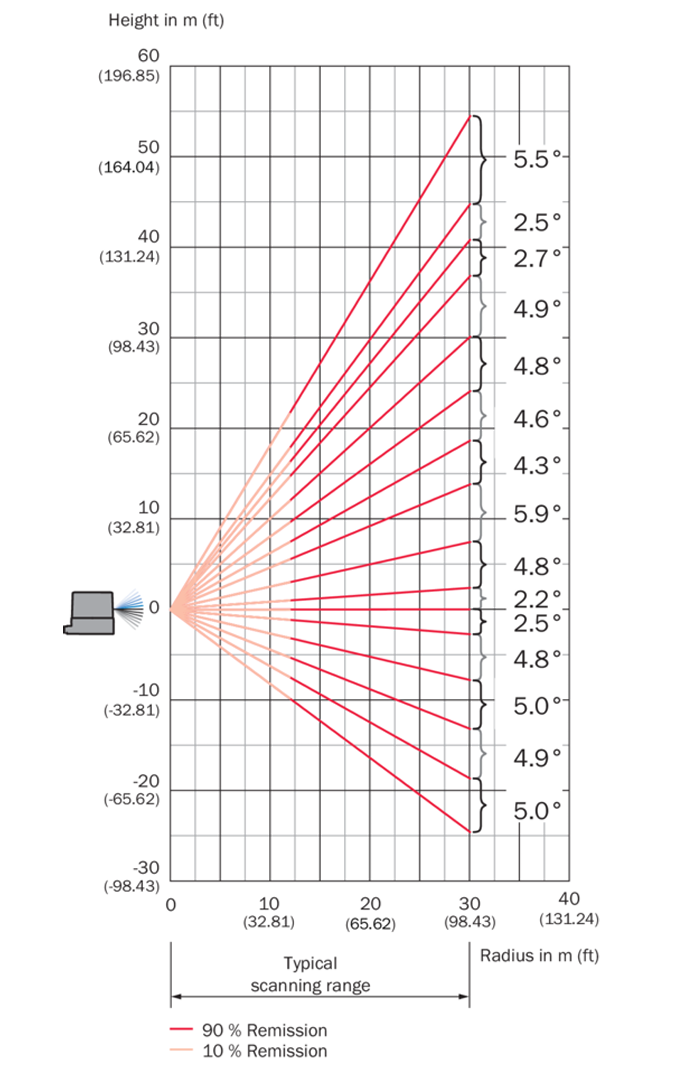
Vertical aperture (total) |
65° |
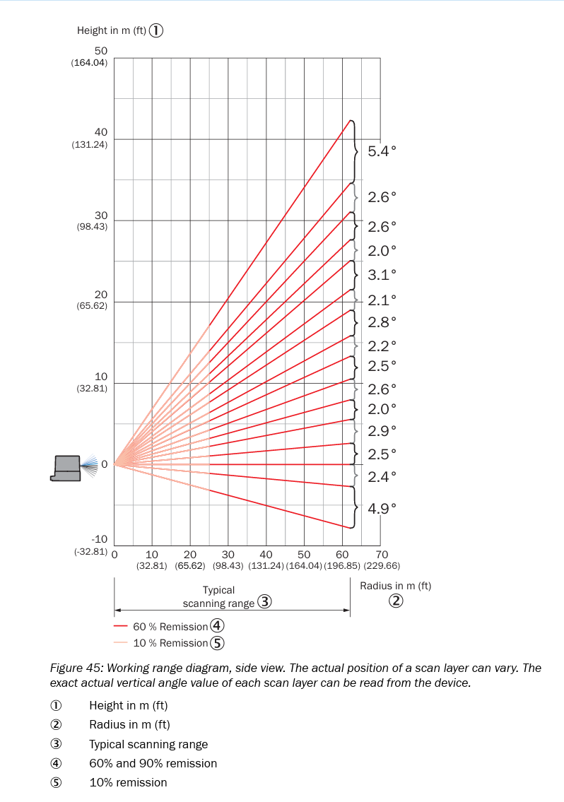
42° |
Vertical angle range (φ) |
+22.5° (up) … −42.5° (down) |
+7.5° (up) … −35° (down) |
Typical vertical spacing |
Approx. 2.5° or 5° between layers (mode-dependent) |
Approx. 2.5° or 5° between layers (mode-dependent) |
Horizontal resolutions / layers |
0.125° on 2 high-res layers, plus 14 layers at 1°; interlaced options: 0.5°/0.125° for 14 layers |
0.125°, 0.25° or 0.5° for all 16 layers, interlaced options |
Extra scan mode |
— |
40 Hz scan between layer 4 and 13 (central vertical band) |
Interpretation of the layer structure
Vertical coverage / application focus
multiScan136
Wider vertical FOV (65°), reaching +22.5° upwards.
Better for applications needing overhead coverage and ground detection.
multiScan165
Narrower vertical FOV (42°), only up to +7.5° upwards.
Focuses its layers where mobile platforms most need detail: horizon and ground region.
Horizontal sampling per layer
multiScan136
Only 2 layers support the finest resolution of 0.125° (20Hz).
Remaining layers use 1° (20Hz), in interlaced mode: 0.5° (10Hz), 0.25° (5Hz)
multiScan165
All 16 layers support 0.5° (20Hz); in interlaced mode: 0.25° (10Hz), 0.125° (5Hz)
Dynamic behavior (central layers)
multiScan165 introduces a 40 Hz mode limited to layers 4–13 for faster reaction in the main obstacle-detection band.
multiScan136 scans uniformly at 20 Hz on all layers.
—.\install
Elevation angle table of multiScan 136
Scan layer |
Measuring module allocation to scan layers |
DIN ISO 8855 (data output) |
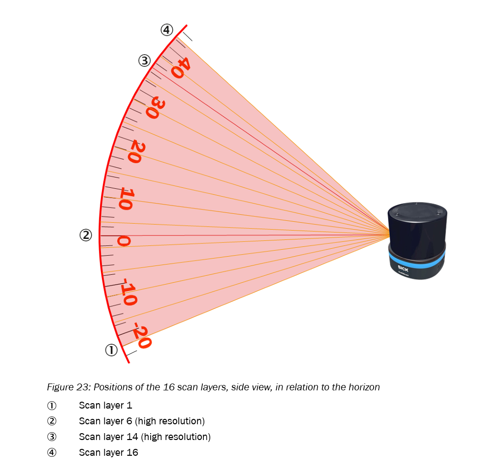
Physical (see following figure for visualization) |
|---|---|---|---|
1 |
Measuring module 0 (looks downwards) |
22.7° |
-22.7° |
2 |
Measuring module 0 |
17.5° |
-17.5° |
3 |
Measuring module 0 |
12.5° |
-12.5° |
4 |
Measuring module 0 |
7.4° |
-7.4° |
5 |
Measuring module 0 |
2.5° |
-2.5° |
6 (high resolution) |
Measuring module 0 |
0° |
0° |
7 |
Measuring module 0 |
-2.4° |
2.4° |
8 |
Measuring module 0 |
-7.3° |
7.3° |
9 |
Measuring module 1 |
-12.8° |
12.8° |
10 |
Measuring module 1 |
-17.3° |
17.3° |
11 |
Measuring module 1 |
-22° |
22° |
12 |
Measuring module 1 |
-26.8° |
26.8° |
13 |
Measuring module 1 |
-31.9° |
31.9° |
14 (high resolution) |
Measuring module 1 |
-34.4° |
34.4° |
15 |
Measuring module 1 |
-37.2° |
37.2° |
16 |
Measuring module 1 (looks upwards) |
-42.8° |
42.8° |
See p. 28/29 in this manual
Elevation angle table of multiScan 165
Scan layer |
Measuring module allocation to scan layers |
DIN ISO 8855 (data output) |
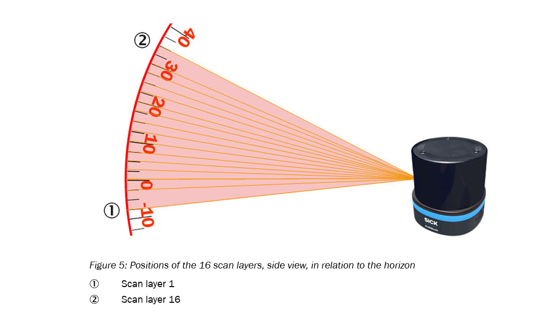
Physical (see following figure for visualization) |
|---|---|---|---|
1 |
Measuring module 0 (looks downwards) |
7.3° |
-7.3° |
2 |
Measuring module 0 |
2.4° |
-2.4° |
3 |
Measuring module 0 |
0.0° |
-0.0° |
4 |
Measuring module 0 |
-2.5° |
2.5° |
5 |
Measuring module 1 |
-5.4° |
5.4° |
6 |
Measuring module 0 |
-7.4° |
7.4° |
7 |
Measuring module 1 |
-10° |
10° |
8 |
Measuring module 0 |
-12.5° |
12.5° |
9 |
Measuring module 1 |
-14.7° |
14.7° |
10 |
Measuring module 0 |
-17.5° |
17.5° |
11 |
Measuring module 1 |
-19.6° |
19.6° |
12 |
Measuring module 0 |
-22.7° |
22.7° |
13 |
Measuring module 1 |
-24.7° |
24.7° |
14 |
Measuring module 1 |
-27.3° |
27.3° |
15 |
Measuring module 1 |
-29.9° |
29.9° |
16 |
Measuring module 1 (looks upwards) |
-35.3° |
35.3° |
See p. 27/28 in this manual
Explanation of the 40 Hz Mode (multiScan165)
Each measuring module of the multiScan165 operates at 20 Hz and transmits data packets containing 8 scan layers. However, in the range of scan layers 4 to 13, the vertical fields of view of the two modules overlap.
In this overlapping elevation region:
Of the 8 layers transmitted by each module, 5 layers overlap (“interlock”) in elevation with the corresponding 5 layers of the other module.
Since both modules operate independently at 20 Hz, but provide measurements in the same elevation range, and are rotated by 180° in azimuth relative to each other, the system receives two complementary data streams for these layers.
As a result, the overlapping layers are effectively updated at 40 Hz, because both modules contribute 20 Hz each for the same set of 5 layers.
In summary:
Each module continues to output 20 Hz × 8 layers, but 5 of these layers lie within the shared elevation range. Since both modules deliver 20 Hz for these layers, the effective update rate becomes 20 Hz + 20 Hz = 40 Hz for this specific vertical segment.
General overview
Advantages of multiScan136:
Maximum vertical coverage.
General-purpose 3D perception including overhead detection.
Advantages of multiScan165:
Uniform fine horizontal resolution across all layers.
Faster update rate in the central vertical region (40 Hz mode).