MyActuator RMD set-up
Author: Tobit Flatscher (2023 - 2024)
0. Connecting to CAN
The actuator will require a 24-48V power supply able to deliver at least 5A. I am using a generic Chinese 48V 10A (480W) S-480-48 power supply from Amazon. I simply modified a socket extension lead and attached it to the power outlet and connected the actuator through a XT30 connector.
You can communicate with the drive through Controller Area Network (CAN bus), a communciations network standard commonly found in automation. For a more detailed brief introduction refer to this article. What should be noted is that every CAN network should be terminated with a 120 Ohm resistor at each end of the bus.
There are several ways to enable a computer to communicate with other devices over CAN:
Some embedded computing boards such as some of the Nvidia Jetson boards already come with integrated CAN controllers. It is sufficient to install a CAN transceiver (that can be had for around 10 USD) and you are ready to go.
For other small single-board computers such as the Raspberry PI one can find simple extension shields such as this one. They will set you back between 50-70 USD.
There are PCI Express cards for desktop computers such as the ones offered by National Instruments but these tend to be quite expensive (in the range of 1000-2000 USD new).
Finally there are small and cost effective USB to CAN adapters, such as the open-source USB to CAN adapter CANable. These may cost between 10 and 200 USD and have the advantage that they can be used with desktop computers, notebooks as well as single-board computers.
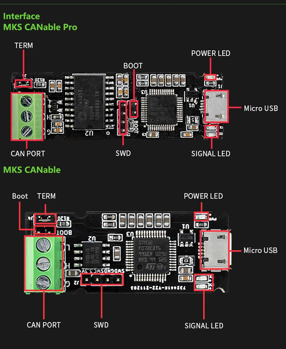
0.1 CANable USB to CAN adapter
The CANable USB to CAN adapter is a low-cost open-source USB to CAN adapter. You can buy them either here or find cheap Chinese copies on Aliexpress. I bought one of the Chinese copies by Makerbase MKS. The corresponding documentaton as well as short video discussing the set-up can be found online.
Theoretically these adapters should work out of the box: It should be sufficient to connect the actuator to the CAN port (with the jumper on in order to activate the terminating resistor) and the board over the USB to your computer. Depending on your set-up you might have to flash the firmware. There are several different firmwares available (I am using Candlelight with my board) that one can choose from. In order to be able to flash a new firmware onto the board depending on the version one will have to move a switch or jumper on the board to a specific position. On my MKS CANable PRO this is done by placing a jumper on the two pins labelled BOOT.
1. Configuring the actuator
The configuration procedure is discussed in this video by the company. Additional downloads can be found on their webpage. The actuator can be optionally configured over an UART serial port connection that comes with it. The configuration GUI, called Assistant 3.0 is sadly only available for Windows. Through it one can configure the actuator addres as well as the baud rate.
2. Testing the actuator
Under Linux we can use SocketCAN as part of the Linux kernel for communicating with the actuator. Examples written in C displaying its usage, including receive filters, can be found here. Additionally there are command line tools available for it, the SocketCAN command line tools, that on Ubuntu can be installed with sudo apt-get install can-utils. An introduction to them can be found here as well as here.
After having connected your actuator through the USB adapter you should be able to see it with
$ ip link show
In my case this outputs a device can0 of the type link/can.
Then continue to configure the CAN interface with
$ sudo ip link set can0 up type can bitrate 500000
where the interface name (in our case can0) must correspond to the previously outputted one and the baud rate has to correspond to the one configured for your drive through the Assistant 3.0 GUI previously.
Finally you can send commands to the corresponding CAN device, specifying its hexadecimal address (again configured in the Assistant 3.0, in my case 141) and the command. The following command will send the actuator to the 360 degree position
$ cansend can0 141#a400f401a08c0000
Similarly
$ cansend can0 141#a400f40100000000
will move the actuator back to 0 degrees.
In case the actuator does not move but it is vibrating it might be that it is already on the corresponding position. If it does not even vibrate, it might be that you send the command to the wrong address. You might want to use Wireshark or candump to see what the error message was returned. An introductory guide to debugging traffic with Wireshark can be found here and a list of corresponding filters is available here.
Finally we can bring the interface down again with
$ sudo ip link set can0 down
Alternatively to the SocketCAN command line tools you might use a graphic user interfaces such as cangaroo. In order to build cangaroo on Linux you might need to build it as well as canifconfig located in the corresponding subfolder and copy both to /usr/bin. For any issues that you might encounter refer to the repository’s issues as well as the issue of the original repository.
3. Debugging this driver
For testing purposes SocketCAN also supports a virtual CAN driver. It can be enabled with
$ sudo modprobe vcan
$ sudo ip link add dev vcan0 type vcan
$ sudo ip link set up vcan0
where vcan0 is the name of the virtual CAN device.
Finally you can test the virtual CAN interface vcan0 by opening two terminals, one for monitoring the received data
$ cansniffer vcan0
and the other for sending it
$ cansend vcan0 141#a400f40100000000
This feature is used for unit testing of this driver.
This driver is based on the RMD-X Servo Motor Control Protocol V3.8. In order to debug it, it might be helpful to get familiar with CANbus errors.