TeleopPanel
The RViz plugin API and library API are preliminary in Fuerte. We welcome feedback about how to make them more powerful and easier to program with. We expect the APIs to change (possibly significantly) between Fuerte and Groovy.
Overview
This tutorial shows how to write a simple Panel plugin for RViz.
A panel in RViz is a GUI widget which can be docked in the main window or floating. It does not show properties in the “Displays” panel like a Display, but it could show things in the 3D scene.
A panel can be a useful place to put a bunch of application-specific GUI elements. You could put start and stop buttons for your robot, or other command or control inputs.
RViz has a built-in tool to send a goal pose to a path planner, but it does not have a native way to send velocity commands directly to a robot base controller. That is what this tutorial shows, a subclass of rviz::Panel which lets you send velocity commands right to your robot.
The source code for this tutorial is in the rviz_plugin_tutorials package. You can check out the source directly or (if you use Ubuntu) you can just apt-get install the pre-compiled Debian package like so:
sudo apt-get install ros-fuerte-visualization-tutorials
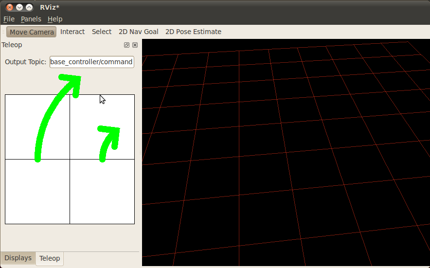
Here is what RViz looks like with the new “Teleop” panel showing on the left:
The Plugin Code
The code for TeleopPanel is in these files: src/teleop_panel.h, src/teleop_panel.cpp, src/drive_widget.h, and src/drive_widget.cpp.
teleop_panel.h
The full text of teleop_panel.h is here: src/teleop_panel.h
Here we declare our new subclass of rviz::Panel. Every panel which can be added via the Panels/Add_New_Panel menu is a subclass of rviz::Panel.
TeleopPanel will show a text-entry field to set the output topic and a 2D control area. The 2D control area is implemented by the DriveWidget class, and is described there.
class TeleopPanel: public rviz::Panel
{
This class uses Qt slots and is a subclass of QObject, so it needs the Q_OBJECT macro.
Q_OBJECT
public:
QWidget subclass constructors usually take a parent widget parameter (which usually defaults to 0). At the same time, pluginlib::ClassLoader creates instances by calling the default constructor (with no arguments). Taking the parameter and giving a default of 0 lets the default constructor work and also lets someone using the class for something else to pass in a parent widget as they normally would with Qt.
TeleopPanel( QWidget* parent = 0 );
Now we declare overrides of rviz::Panel functions for saving and loading data from a config file, in this case the topic name.
virtual void saveToConfig( const std::string& key_prefix, const boost::shared_ptr<rviz::Config>& config );
virtual void loadFromConfig( const std::string& key_prefix, const boost::shared_ptr<rviz::Config>& config );
Next come a couple of public Qt slots.
public Q_SLOTS:
The control area, DriveWidget, sends its output to a Qt signal for ease of re-use, so here we declare a Qt slot to receive it.
void setVel( float linear_velocity_, float angular_velocity_ );
In this example setTopic() does not get connected to any signal (it is called directly), but it is easy to define it as a public slot instead of a private function in case it would be useful to some other user.
void setTopic( const std::string& topic );
Here we declare some internal slots.
protected Q_SLOTS:
sendvel() publishes the current velocity values to a ROS topic. Internally this is connected to a timer which calls it 10 times per second.
void sendVel();
updateTopic() reads the topic name from the QLineEdit and calls setTopic() with the result.
void updateTopic();
Then we finish up with protected member variables.
protected:
The control-area widget which turns mouse events into command velocities.
DriveWidget* drive_widget_;
One-line text editor for entering the outgoing ROS topic name.
QLineEdit* output_topic_editor_;
The current name of the output topic.
std::string output_topic_;
The ROS publisher for the command velocity.
ros::Publisher velocity_publisher_;
The ROS node handle.
ros::NodeHandle nh_;
The latest velocity values from the drive widget.
float linear_velocity_;
float angular_velocity_;
teleop_panel.cpp
The full text of teleop_panel.cpp is here: src/teleop_panel.cpp
Here is the implementation of the TeleopPanel class. TeleopPanel has these responsibilities:
- Act as a container for GUI elements DriveWidget and QLineEdit.
- Publish command velocities 10 times per second (whether 0 or not).
- Saving and restoring internal state from a config file.
We start with the constructor, doing the standard Qt thing of passing the optional parent argument on to the superclass constructor, and also zero-ing the velocities we will be publishing.
TeleopPanel::TeleopPanel( QWidget* parent )
  : rviz::Panel( parent )
  , linear_velocity_( 0 )
  , angular_velocity_( 0 )
{
Next we lay out the “output topic” text entry field using a QLabel and a QLineEdit in a QHBoxLayout.
QHBoxLayout* topic_layout = new QHBoxLayout;
topic_layout->addWidget( new QLabel( "Output Topic:" ));
output_topic_editor_ = new QLineEdit;
topic_layout->addWidget( output_topic_editor_ );
Then create the control widget.
drive_widget_ = new DriveWidget;
Lay out the topic field above the control widget.
QVBoxLayout* layout = new QVBoxLayout;
layout->addLayout( topic_layout );
layout->addWidget( drive_widget_ );
setLayout( layout );
Create a timer for sending the output. Motor controllers want to be reassured frequently that they are doing the right thing, so we keep re-sending velocities even when they aren’t changing.
Here we take advantage of QObject’s memory management behavior: since “this” is passed to the new QTimer as its parent, the QTimer is deleted by the QObject destructor when this TeleopPanel object is destroyed. Therefore we don’t need to keep a pointer to the timer.
QTimer* output_timer = new QTimer( this );
Next we make signal/slot connections.
connect( drive_widget_, SIGNAL( outputVelocity( float, float )), this, SLOT( setVel( float, float )));
connect( output_topic_editor_, SIGNAL( editingFinished() ), this, SLOT( updateTopic() ));
connect( output_timer, SIGNAL( timeout() ), this, SLOT( sendVel() ));
Start the timer.
output_timer->start( 100 );
Make the control widget start disabled, since we don’t start with an output topic.
  drive_widget_->setEnabled( false );
}
setVel() is connected to the DriveWidget’s output, which is sent whenever it changes due to a mouse event. This just records the values it is given. The data doesn’t actually get sent until the next timer callback.
void TeleopPanel::setVel( float lin, float ang )
{
  linear_velocity_ = lin;
  angular_velocity_ = ang;
}
Read the topic name from the QLineEdit and call setTopic() with the results. This is connected to QLineEdit::editingFinished() which fires when the user presses Enter or Tab or otherwise moves focus away.
void TeleopPanel::updateTopic()
{
  setTopic( output_topic_editor_->text().toStdString() );
}
Set the topic name we are publishing to.
void TeleopPanel::setTopic( const std::string& new_topic )
{
Only take action if the name has changed.
if( new_topic != output_topic_ )
{
  output_topic_ = new_topic;
If the topic is the empty string, don’t publish anything.
if( output_topic_ == "" )
{
  velocity_publisher_.shutdown();
}
else
{
The old velocity_publisher_ is destroyed by this assignment, and thus the old topic advertisement is removed. The call to nh_advertise() says we want to publish data on the new topic name.
  velocity_publisher_ = nh_.advertise<geometry_msgs::Twist>( output_topic_, 1 );
}
rviz::Panel defines the configChanged() signal. Emitting it tells RViz that something in this panel has changed that will affect a saved config file. Ultimately this signal can cause QWidget::setWindowModified(true) to be called on the top-level rviz::VisualizationFrame, which causes a little asterisk (“*”) to show in the window’s title bar indicating unsaved changes.
  Q_EMIT configChanged();
}
Gray out the control widget when the output topic is empty.
  drive_widget_->setEnabled( output_topic_ != "" );
}
Publish the control velocities if ROS is not shutting down and the publisher is ready with a valid topic name.
void TeleopPanel::sendVel()
{
  if( ros::ok() && velocity_publisher_ )
  {
    geometry_msgs::Twist msg;
    msg.linear.x = linear_velocity_;
    msg.linear.y = 0;
    msg.linear.z = 0;
    msg.angular.x = 0;
    msg.angular.y = 0;
    msg.angular.z = angular_velocity_;
    velocity_publisher_.publish( msg );
  }
}
Save all configuration data from this panel to the given Config object. It is important here that you append the key_prefix to all keys you use, so that your settings don’t collide with settings from other components.
void TeleopPanel::saveToConfig( const std::string& key_prefix, const boost::shared_ptr<rviz::Config>& config )
{
  config->set( key_prefix + "/Topic", output_topic_ );
}
Load all configuration data for this panel from the given Config object. It is important here that you append the key_prefix to all keys you use, so that your settings don’t collide with settings from other components.
void TeleopPanel::loadFromConfig( const std::string& key_prefix, const boost::shared_ptr<rviz::Config>& config )
{
  std::string topic;
  config->get( key_prefix + "/Topic", &topic );
  output_topic_editor_->setText( QString::fromStdString( topic ));
  updateTopic();
}

} // end namespace rviz_plugin_tutorials
Tell pluginlib about this class. Every class which should be loadable by pluginlib::ClassLoader must have these two lines compiled in its .cpp file, outside of any namespace scope.
#include <pluginlib/class_list_macros.h>
PLUGINLIB_DECLARE_CLASS( rviz_plugin_tutorials, Teleop, rviz_plugin_tutorials::TeleopPanel, rviz::Panel )
drive_widget.h
The full text of drive_widget.h is here: src/drive_widget.h
DriveWidget implements a control which translates mouse Y values into linear velocities and mouse X values into angular velocities.
For maximum reusability, this class is only responsible for user interaction and display inside its widget. It does not make any ROS or RViz calls. It communicates its data to the outside just via Qt signals.
class DriveWidget: public QWidget
{
Q_OBJECT
public:
This class is not instantiated by pluginlib::ClassLoader, so the constructor has no restrictions.
DriveWidget( QWidget* parent = 0 );
We override QWidget::paintEvent() to do custom painting.
virtual void paintEvent( QPaintEvent* event );
We override the mouse events and leaveEvent() to keep track of what the mouse is doing.
virtual void mouseMoveEvent( QMouseEvent* event );
virtual void mousePressEvent( QMouseEvent* event );
virtual void mouseReleaseEvent( QMouseEvent* event );
virtual void leaveEvent( QEvent* event );
Override sizeHint() to give the layout managers some idea of a good size for this.
virtual QSize sizeHint() const { return QSize( 150, 150 ); }
We emit outputVelocity() whenever it changes.
Q_SIGNALS:
  void outputVelocity( float linear, float angular );
mouseMoveEvent() and mousePressEvent() need the same math to figure the velocities, so I put that in here.
protected:
  void sendVelocitiesFromMouse( int x, int y, int width, int height );
A function to emit zero velocity.
void stop();
Finally the member variables:
  float linear_velocity_; // In m/s
  float angular_velocity_; // In radians/s
  float linear_scale_; // In m/s
  float angular_scale_; // In radians/s
};
drive_widget.cpp
The full text of drive_widget.cpp is here: src/drive_widget.cpp
The DriveWidget constructor does the normal Qt thing of passing the parent widget to the superclass constructor, then initializing the member variables.
DriveWidget::DriveWidget( QWidget* parent )
  : QWidget( parent )
  , linear_velocity_( 0 )
  , angular_velocity_( 0 )
  , linear_scale_( 10 )
  , angular_scale_( 2 )
{
}
This paintEvent() is complex because of the drawing of the two arc-arrows representing wheel motion. It is not particularly relevant to learning how to make an RViz plugin, so I will kind of skim it.
void DriveWidget::paintEvent( QPaintEvent* event )
{
The background color and crosshair lines are drawn differently depending on whether this widget is enabled or not. This gives a nice visual indication of whether the control is “live”.
QColor background;
QColor crosshair;
if( isEnabled() )
{
  background = Qt::white;
  crosshair = Qt::black;
}
else
{
  background = Qt::lightGray;
  crosshair = Qt::darkGray;
}
The main visual is a square, centered in the widget’s area. Here we compute the size of the square and the horizontal and vertical offsets of it.
int w = width();
int h = height();
int size = (( w > h ) ? h : w) - 1;
int hpad = ( w - size ) / 2;
int vpad = ( h - size ) / 2;

QPainter painter( this );
painter.setBrush( background );
painter.setPen( crosshair );
Draw the background square.
painter.drawRect( QRect( hpad, vpad, size, size ));
Draw a cross-hair inside the square.
painter.drawLine( hpad, height() / 2, hpad + size, height() / 2 );
painter.drawLine( width() / 2, vpad, width() / 2, vpad + size );
If the widget is enabled and the velocities are not zero, draw some sweet green arrows showing possible paths that the wheels of a diff-drive robot would take if it stayed at these velocities.
if( isEnabled() && (angular_velocity_ != 0 || linear_velocity_ != 0 ))
{
  QPen arrow;
  arrow.setWidth( size/20 );
  arrow.setColor( Qt::green );
  arrow.setCapStyle( Qt::RoundCap );
  arrow.setJoinStyle( Qt::RoundJoin );
  painter.setPen( arrow );
This code steps along a central arc defined by the linear and angular velocites. At each step, it computes where the left and right wheels would be and collects the resulting points in the left_track and right_track arrays.
int step_count = 100;
QPointF left_track[ step_count ];
QPointF right_track[ step_count ];

float half_track_width = size/4.0;

float cx = w/2;
float cy = h/2;
left_track[ 0 ].setX( cx - half_track_width );
left_track[ 0 ].setY( cy );
right_track[ 0 ].setX( cx + half_track_width );
right_track[ 0 ].setY( cy );
float angle = M_PI/2;
float delta_angle = angular_velocity_ / step_count;
float step_dist = linear_velocity_ * size/2 / linear_scale_ / step_count;
for( int step = 1; step < step_count; step++ )
{
  angle += delta_angle / 2;
  float next_cx = cx + step_dist * cosf( angle );
  float next_cy = cy - step_dist * sinf( angle );
  angle += delta_angle / 2;

  left_track[ step ].setX( next_cx + half_track_width * cosf( angle + M_PI/2 ));
  left_track[ step ].setY( next_cy - half_track_width * sinf( angle + M_PI/2 ));
  right_track[ step ].setX( next_cx + half_track_width * cosf( angle - M_PI/2 ));
  right_track[ step ].setY( next_cy - half_track_width * sinf( angle - M_PI/2 ));

  cx = next_cx;
  cy = next_cy;
}
Now the track arrays are filled, so stroke each with a fat green line.
painter.drawPolyline( left_track, step_count );
painter.drawPolyline( right_track, step_count );
Here we decide which direction each arrowhead will point (forward or backward). This works by comparing the arc length travelled by the center in one step (step_dist) with the arc length travelled by the wheel (half_track_width * delta_angle).
int left_arrow_dir = (-step_dist + half_track_width * delta_angle > 0);
int right_arrow_dir = (-step_dist - half_track_width * delta_angle > 0);
Use MiterJoin for the arrowheads so we get a nice sharp point.
arrow.setJoinStyle( Qt::MiterJoin );
painter.setPen( arrow );
Compute and draw polylines for each arrowhead. This code could probably be more elegant.
    float head_len = size / 8.0;
    QPointF arrow_head[ 3 ];
    float x, y;
    if( fabsf( -step_dist + half_track_width * delta_angle ) > .01 )
    {
      x = left_track[ step_count - 1 ].x();
      y = left_track[ step_count - 1 ].y();
      arrow_head[ 0 ].setX( x + head_len * cosf( angle + 3*M_PI/4 + left_arrow_dir * M_PI ));
      arrow_head[ 0 ].setY( y - head_len * sinf( angle + 3*M_PI/4 + left_arrow_dir * M_PI ));
      arrow_head[ 1 ].setX( x );
      arrow_head[ 1 ].setY( y );
      arrow_head[ 2 ].setX( x + head_len * cosf( angle - 3*M_PI/4 + left_arrow_dir * M_PI ));
      arrow_head[ 2 ].setY( y - head_len * sinf( angle - 3*M_PI/4 + left_arrow_dir * M_PI ));
      painter.drawPolyline( arrow_head, 3 );
    }
    if( fabsf( -step_dist - half_track_width * delta_angle ) > .01 )
    {
      x = right_track[ step_count - 1 ].x();
      y = right_track[ step_count - 1 ].y();
      arrow_head[ 0 ].setX( x + head_len * cosf( angle + 3*M_PI/4 + right_arrow_dir * M_PI ));
      arrow_head[ 0 ].setY( y - head_len * sinf( angle + 3*M_PI/4 + right_arrow_dir * M_PI ));
      arrow_head[ 1 ].setX( x );
      arrow_head[ 1 ].setY( y );
      arrow_head[ 2 ].setX( x + head_len * cosf( angle - 3*M_PI/4 + right_arrow_dir * M_PI ));
      arrow_head[ 2 ].setY( y - head_len * sinf( angle - 3*M_PI/4 + right_arrow_dir * M_PI ));
      painter.drawPolyline( arrow_head, 3 );
    }
  }
}
Every mouse move event received here sends a velocity because Qt only sends us mouse move events if there was previously a mouse-press event while in the widget.
void DriveWidget::mouseMoveEvent( QMouseEvent* event )
{
  sendVelocitiesFromMouse( event->x(), event->y(), width(), height() );
}
Mouse-press events should send the velocities too, of course.
void DriveWidget::mousePressEvent( QMouseEvent* event )
{
  sendVelocitiesFromMouse( event->x(), event->y(), width(), height() );
}
When the mouse leaves the widget but the button is still held down, we don’t get the leaveEvent() because the mouse is “grabbed” (by default from Qt). However, when the mouse drags out of the widget and then other buttons are pressed (or possibly other window-manager things happen), we will get a leaveEvent() but not a mouseReleaseEvent(). Without catching this event you can have a robot stuck “on” without the user controlling it.
void DriveWidget::leaveEvent( QEvent* event )
{
  stop();
}
The ordinary way to stop: let go of the mouse button.
void DriveWidget::mouseReleaseEvent( QMouseEvent* event )
{
  stop();
}
Compute and emit linear and angular velocities based on Y and X mouse positions relative to the central square.
void DriveWidget::sendVelocitiesFromMouse( int x, int y, int width, int height )
{
  int size = (( width > height ) ? height : width );
  int hpad = ( width - size ) / 2;
  int vpad = ( height - size ) / 2;

  linear_velocity_ = (1.0 - float( y - vpad ) / float( size / 2 )) * linear_scale_;
  angular_velocity_ = (1.0 - float( x - hpad ) / float( size / 2 )) * angular_scale_;
  Q_EMIT outputVelocity( linear_velocity_, angular_velocity_ );
update() is a QWidget function which schedules this widget to be repainted the next time through the main event loop. We need this because the velocities have just changed, so the arrows need to be redrawn to match.
  update();
}
How to stop: emit velocities of 0!
void DriveWidget::stop()
{
  linear_velocity_ = 0;
  angular_velocity_ = 0;
  Q_EMIT outputVelocity( linear_velocity_, angular_velocity_ );
  update();
}
Building the Plugin
To build the plugin, just do the normal “rosmake” thing:
rosmake rviz_plugin_tutorials
Exporting the Plugin
For the plugin to be found and understood by other ROS packages (in this case, rviz), it needs a “plugin_description.xml” file. This file can be named anything you like, as it is specified in the plugin package’s “manifest.xml” file like so:
<export>
    <rviz plugin="${prefix}/plugin_description.xml"/>
</export>
The contents of plugin_description.xml then look like this:
<library path="lib/librviz_plugin_tutorials">
  <class name="rviz_plugin_tutorials/Teleop"
         type="rviz_plugin_tutorials::TeleopPanel"
         base_class_type="rviz::Panel">
    <description>
      A panel widget allowing simple diff-drive style robot base control.
    </description>
  </class>
  <class name="rviz_plugin_tutorials/Imu"
         type="rviz_plugin_tutorials::ImuDisplay"
         base_class_type="rviz::Display">
    <description>
      Displays direction and scale of accelerations from sensor_msgs/Imu messages.
    </description>
  </class>
</library>
The first line says that the compiled library lives in lib/librviz_plugin_tutorials (the ”.so” ending is appended by pluginlib according to the OS). This path is relative to the top directory of the package:
<library path="lib/librviz_plugin_tutorials">
The next section is a class entry describing the TeleopPanel:
<class name="rviz_plugin_tutorials/Teleop"
       type="rviz_plugin_tutorials::TeleopPanel"
       base_class_type="rviz::Panel">
  <description>
    A panel widget allowing simple diff-drive style robot base control.
  </description>
</class>
This specifies the name, type, base class, and description of the class. The name field must be a combination of the first two strings given to the PLUGINLIB_DECLARE_CLASS() macro in the source file. It must be the “package” name, a “/” slash, then the “display name” for the class.
The type entry must be the fully-qualified class name, including any namespace(s) it is inside.
The base_class_type is either rviz::Panel for a panel class, or rviz::Display for a display class.
The description subsection is a simple text description of the class, which is shown in the class-chooser dialog and in the Displays panel help area. This section can contain HTML, including hyperlinks, but the markup must be escaped to avoid being interpreted as XML markup. For example a link tag might look like: <a href="my-web-page.html">.
Trying It Out
Once your RViz plugin is compiled and exported, simply run rviz normally:
rosrun rviz rviz
and rviz will use pluginlib to find all the plugins exported to it.
Add a Teleop panel by opening the “Panels” menu and then “Add New Panel” within that. This should bring up a Panel class chooser dialog with “Teleop” in it (here it is “rviz_plugin_tutorials”):
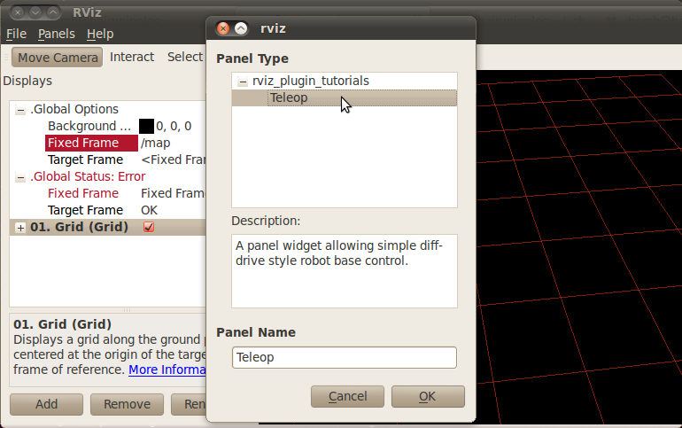
If “Teleop” is not in your list of Panel types, look through RViz’s console output for error messages relating to plugin loading. Some common problems are:
- not having a plugin_description.xml file,
- not exporting it in the manifest.xml file, or
- not properly referencing the library file (like librviz_plugin_tutorials.so) from plugin_description.xml.
Once you’ve added the Teleop panel to RViz, you just need to enter a topic name to publish the geometry_msgs/Twist command velocities on. Once a non-empty string has been entered in the “Output Topic” field, the control square area should light up and accept mouse events. Holding the mouse button down in the control area sends a linear velocity based on the Y position of the mouse relative to the center and an angular velocity based on the X position of the mouse relative to the center.
Next Steps
This Teleop panel might be useful as it is, since it already sends out command velocities appropriate for a diff-drive robot. However, there are a few things which might make it more useful:
- Adjustable scaling of the linear and angular velocities.
- Enforced maxima for the velocities.
- An adjustable robot width parameter, so that the curved arrows accurately show the arc a robot would traverse.
- A “strafe” mode (maybe when holding down the Shift key) for robots like the PR2 with (more) holonomic drive ability.
Conclusion
Remember, the plugin API for RViz is still preliminary. I think there are a number of ways the process of writing a plugin can be streamlined before the Groovy release. In the meantime, please try out this Fuerte API version and let us know what you think!