Sensor Configuration and Data Output
Overview
This section gives you an overview of the configuration options and data output of your sensor. For more detailed and sensor-specfic explanations please see the documentation for the respective sensors. Furthermore, a detailed description of the orientation sensor fusion and how to optimize it for your application case can be found there.
Data Output Settings
Will all sensors models, the data which is transmitted can be selected individually to save bandwith and improve the latency of the data transfer. Therefore, you need to ensure the data item you want to read out is enabled for output. There are two ways to enable or disable the output of a data item.
1. Use the graphical user interface tools
- LPMSControl2: for LPMS3 sensors.
- OpenMAT: for LPMS2 sensors
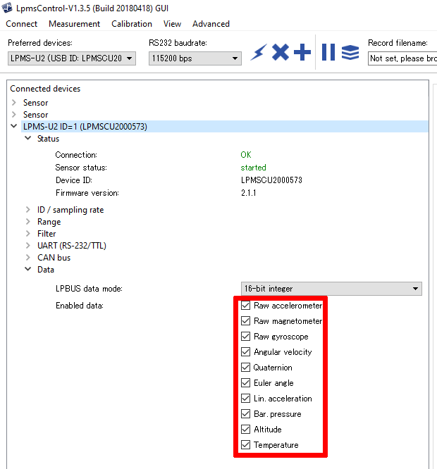
IO Systems gives an overview of LPMS2/3 sensors. You can download these tools from our support website. Then connect to the sensor and enable the output of the data you require. After enabling the output please ensure the settings are persisent by writing them to the sensor flash.
Here is an example where to change the sensor data output on OpenMAT:
2. Configure data output with OpenZen
You can also enable or disable the output data set with OpenZen after you have opened a connection to the sensor:
imu.setBoolProperty(ZenImuProperty_OutputEuler, false);
imu.setBoolProperty(ZenImuProperty_OutputRawGyr, true);
...
Inertial Data: ZenImuData
The ZenImuData structure contains the measurements of accelerometer and gyroscope sensors. Data items which are not enabled for output or not supported by the sensor are kept at their default values. This data structure will be output by all LP-Research sensors. The latest data structure could be found in ZenTypes.h.
| Field Name | Unit | Description |
|---|---|---|
frameCount
|
no unit
|
Data frame number assigned to this
measurement by the firmware.
|
timestamp
|
s
|
Timestamp of the measurement data.
The start point of this timestamp
is arbitrary but subsequent
|
a
|
g
|
Accleration measurment after all
corrections have been applied
|
g0
|
deg/s
|
Gyro I measurment after all
corrections have been applied
|
g1
|
deg/s
|
Gyro II measurment after all
corrections have been applied
|
b
|
Magnetometer measurment after all
corrections have been applied
|
|
aRaw
|
m/s^2
|
Accleration measurment before all
corrections have been applied
|
gRaw
|
deg/s
|
Gyroscope measurment before all
corrections have been applied
|
w
|
deg/s
|
Angular veloctiy.
This angular velocity takes into
account if an orientation offset
has been.
|
r
|
deg/s
|
Three euler angles representing
See the sensor documenation how
the angles are defined
|
q
|
no unit
|
rotation of the sensor in this
order: w, x, y,z
rotation axes are defined.
|
rotationM
|
no unit
|
rotation matrix without offset
applied.
|
rotOffsetM
|
no unit
|
.
|
pressure
|
mPa
|
|
m
|
Heave motion output.
|
Global Position: ZenGnssData
The ZenGnssData structure contains the measurements of a global navigation satellite system (GNSS) receiver. It is only availbable if the sensor contains a GNSS component. Most receivers combine their position measurements from multiple satellite constelations like GPS, Galileo or GLONASS.
To receive all GNSS data listed below, all output options of the form
ZenGnssProperty_OutputNavPvt* need to be enabled.
| Field Name | Unit | Description |
|---|---|---|
| timestamp | s | Timestamp of the measurement data. The start point of this timestamp is arbitrary but subsequent measurements are guaranteed to have the distance to each other in time. |
| latitude | degrees | Latitude measurement provided by the GNSS or the IMU/GNSS sensor fusion. |
| horizontalAccuracy | m | Accuracy of the horizontal measurement |
| longitude | degrees | Longitude measurement provided by the GNSS or the IMU/GNSS sensor fusion. |
| verticalAccuracy | m | Accuracy of the vertical measurement |
| height | m | height above WGS84 ellipsoid |
| headingOfMotion | degrees | Heading of sensor motion in degrees in clockwise counting and 0 degree being north. |
| headingOfVehicle | degrees | Heading of vehicle in degrees in clockwise counting and 0 degree being north. Can only be used when the IMU/GPS sensor fusion is active This heading is not changing if the vehicle drives backwards for example. |
| headingAccuracy | degrees | Heading Accuracy in degrees for both headingOfVehicle and headingOfMotion. |
| velocity | m/s | Velocity over ground |
| velocityAccuracy | m/s | velocity accuracy over ground |
| fixType | enumeration | type of the GNSS fix and if dead-reckoning mode is active. |
| carrierPhaseSolution | enumeration | Information if an additional RTK carrier phase correction is used. |
| numberSatellitesUsed | no unit | the number of satellites that have been used to compute the position. |
| year | years | GNSS Year in UTC. |
| month | months | GNSS Month in UTC. |
| day | days | GNSS Day in UTC. |
| hour | hours | GNSS Hour in UTC |
| minute | minutes | GNSS Minute in UTC |
| second | s | GNSS Second in UTC |
| nanoSecondCorrection | ns | This is the time in nanoseconds which the above date and time values need to be shifted to arrive at the exact time point measured using the GNSS receiver. |